Equipment for digital television - this is what you can buy in our store. Instructions for making a television antenna for a summer residence with your own hands
10.10. UHF Antennas
In the AMV range, due to a decrease in the effective length of the receiving antenna, with increasing frequency, a lower voltage develops at the antenna input than under the same conditions in the meter range. Therefore, it becomes necessary to install antennas with a high gain. In antennas of the "Wave channel" type, this is achieved by increasing the number of directors, creating in-phase arrays from multi-element antennas (Fig. 10.30). Since the dimensions of the antenna elements of adjacent channels differ slightly, they are usually given for a group of channels (Table 10.20).
Table 10.20
13-element antenna type "Wave channel" consists of three reflectors, an active loop vibrator and 9 directors. The distance between the ends of the loop vibrator A is 10...20 mm. The diameter of the antenna vibrators is 4...8 mm. The antenna gain is 11.5 dB, the opening angle of the main lobe of the radiation pattern in the horizontal and vertical planes is 40°.
19-element wave channel antenna for the UHF range (Fig. 10.31) consists of three reflectors, an active loop vibrator and 15 directors. The vibrators are made of wire and tubes with a diameter of 4 mm. They are attached in any way to the carrier boom with a diameter of 20 mm. The boom length for any channel group is 2145 mm (Table 10.21). The antenna gain is 14...15 dB, the opening angle of the main lobe of the radiation pattern in the horizontal and vertical planes is 30...32.
Broadband antenna of the "Wave channel" type for reception in channels 21 ... 41(Fig. 10.32).
Depending on the distance to the television transmitter and the zone of reliable reception of its signals, the number of elements (directors) of the antenna can be reduced to 8.11 or 15.
In the case when preference is given to reception in one television channel (for example, reception of an NTV program from Kolodishchi), the dimensions of the antenna elements and the distances between them can be recalculated for this channel.
Table 10.21
The UHF broadband antenna has the highest gain (13 dB) in the 28th channel, the average frequency of which is 500 MHz. The conversion factor (Kp) in this case is determined by the formula
Kp=530/fcp
where fcp is the average frequency of the UHF channel, MHz. For the 37th channel, the average frequency of which is 562 MHz, Kp is equal to:
Kp=530/562=0.943.
Multiplying the dimensions of the elements and the distance between them by 0.943, we obtain the dimensions of the antenna for the 37th channel (Fig. 10.33). You can also recalculate a broadband antenna for any channel (or group of channels) of the UHF. The average frequency of the channel (group of channels) is given in Table. 10.2, the length of the half-wave loop - in table. 10.1. When using a metal carrier boom (traverse), the dimensions of the elements obtained during recalculation are increased by half of its diameter.
The gain of the channel antenna increases to 14...15 dB. An antenna of eight elements is used at a distance of up to 20 ... 30 km from the village. Kolodishchi, from 11 - up to 30 ... 40, from 15 elements - up to 50 ... 60 km. Behind the zone of reliable reception at a distance of up to 70 ... 90 km, an antenna of 24 elements is used. To provide good quality of the received image, an antenna amplifier is installed directly on the mast.
The antenna is little influenced by nearby objects and has good repeatability. Deviations of up to 2 mm from the calculated dimensions are permissible with virtually no deterioration in the antenna parameters.
Antenna type "Wave channel" with a complex passive reflector(Fig. 10.34; tables 10.22 ... 10.24) consists of a lattice reflector (Fig. 10.35, a), two sheets of which are installed at an angle of 90 ° at the end of the carrying boom, an active loop vibrator (Fig. 10.35, b) and 18 directors.
At the same time, the first two directors (A1 and D2) are two-story and spaced vertically by the thickness of the carrier boom (Table 10.23).
Table 10.22
The main advantage of such an antenna is the reliable screening of the rear hemisphere due to an increase in the coefficient of protection when installing a complex reflector. The latter concentrates the energy of the useful signal in the direction of the active vibrator, which helps to increase the gain of the antenna.
Table 10.23
Table 10.24
On fig. 10.36 shows a side view of the antenna described above. The 6-element antenna is designed for short-range reception at a distance of up to 10 ... 15 km from a television transmitter:
10-element - 15...25; 15-element - 25...40; 20-element - at a distance of 40 ... 60 km or more.
In the UHF range are widely used loop Antenna Triple Square, whose frames are made of whole piece copper, brass wire with a diameter of 2 ... 3 mm. With the dimensions of the decimeter range (Table 10.25), the antenna has sufficient rigidity. The wire must be bent in a certain way (Fig. 10.37). At points A, B and C, the wires must be stripped and soldered. In this design, instead of a loop (see Fig. 10.12), made from a piece of coaxial cable, a quarter-wave short is used.
a closed bridge (see Fig. 10.11) of the same length as the loop (see Table 10.5). The distance between the bridge wires remains the same (30 mm). The design of such an antenna is quite rigid, and the lower boom is not needed here.
The feeder is tied to the right wire of the bridge from the outside. When the feeder approaches the vibrator frame, the cable braid is soldered to point X "the central conductor is to point X. The left wire of the bridge is fixed on a dielectric stand or, in the case of an external antenna, on a mast. It is important that there is no feeder and mast stand in the space between the wires of the bridge .
In the presence of copper, brass or aluminum strips
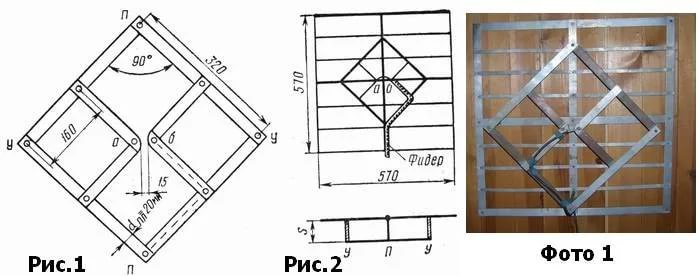
can be done diamond-shaped antenna(Fig. 10.38). The strips (1) are overlapped with screws and nuts. There must be reliable electrical contact at the point of contact between the plates. The thickness of the strips is arbitrary.
A diamond-shaped antenna can operate in the frequency band of channels 21 ... 60, its gain is 6 ... 8 dB. To increase it, the antenna can be equipped with a reflector (Fig. 10.39).
The simplest reflector is a flat screen made of tubes or pieces of thick wire. The diameter of the reflector elements is not critical (3...10 mm). The reflector sheet (2) is fixed with the support stands (3)
Table 10.25
to a metal or wooden mast (4). Points 0 have zero potential, relative to the ground, so the posts (2) can be metal.
Feeder (5) - a RK type cable with a wave impedance of 75 Ohm is laid to power points A and B. The cable braid is soldered to point B, and the central conductor to point A. At long-range reception, the diamond-shaped antenna can be equipped with a broadband amplifier (6).
2-element Swiss antenna(see Fig. 10.21) can also be used in the UHF range (Table 10.26).
Previously, it was difficult to purchase a ready-made high-quality television antenna. Craftsmen, using radio engineering knowledge, designed independently decent samples that soundly receive the ether signal. Times have changed, digital television has replaced analog television, but the problem of having a good decimeter antenna in places with difficult conditions remains relevant.
The evolution of broadcasting
There have been a number of changes in broadcasting that must be considered before making a decimeter antenna with your own hands:
- Now almost all TV broadcasting is done in the UHF band. One of the reasons - economic factor. The equipment of transmitting stations: antennas, feeders are significantly cheaper. The need for their preventive maintenance by highly qualified specialists is reduced;
- The TV signal covers all places that were previously inaccessible. In "blind corners" coverage is provided by an unattended transmitter;
- The digital television signal has its own character traits. He feels little interference, but if the cable is mismatched, or there are phase distortions in any place of the receiving-transmitting path, the image can “tear” even when high quality signal;
- Television has a huge number of programs, and it makes no sense to tune the UHF antenna to several channels;
- Urban conditions for the transmission of waves have been transformed due to the rapid construction of multi-storey buildings, the reinforced concrete buildings of which are able to repeatedly reflect them until they gradually fade.
The length of the DW wave is in the range of 0.1-1 m. Hence its name. Electromagnetic waves can only propagate in the forward direction, without bending around obstacles. Therefore, for a long distance, such a connection is problematic. Its coverage radius is 100 km. The decimeter range antenna must be manufactured taking into account the changed requirements.
Modern requirements
- Previously, the determining value was assigned to the coefficients of directional and protective action. Now this is not so. The ether has become heavily polluted, and it is necessary to overcome interference by electronic means;
- The individual antenna gain comes first. Such a UHF antenna can create the necessary margin of safety for the signal, which will subsequently be processed by electronics;
- It is important to ensure the smoothness of the frequency response. Sharp peaks and falls will cause phase distortion;
- Coordination with the cable over the entire frequency range must be complete without the use of additional devices;
- Antenna parameters must comply with the requirements in the entire frequency range initially. A band antenna does not need to be artificially adapted using engineering tricks.
Properties of different types of antennas
Antennas acceptable for self-manufacturing:
- All-wave. Does not depend on frequency. UHF antenna with the lowest parameters. But to make it the most simple and cheap. It is good to use it for a TV in a country house, where, in conditions of relatively clean air, the device can receive a digital signal. Perfectly copes with the reception of an analog signal near the television center;
- Log-periodic range. It is also an easy option. Matches the outgoing feeder exactly in its range. It filters out certain frequencies. It has average characteristics. It serves well as an indoor antenna in a city house or apartment;
- Zigzag or Z-type. If this is an MV antenna, then making it is much more difficult. Complicated calculations are required and a lot of time is spent on manufacturing. In the decimeter range, all dimensions are reduced, calculations are simplified, and an effective antenna for indoor or outdoor use is obtained in virtually any signal quality.
Important! Perfect matching and symmetry of the antenna can be achieved by laying the cable through "zero" (a point with zero potential, where the currents are maximum and the voltage is zero).
Antenna parameters
A do-it-yourself decimeter antenna can be made with a minimum of theoretical knowledge, but it is necessary to practically understand the meaning of its parameters.
- Gain (GA) is the relative increase in radiation at the time of the peak, the magnitude of which (dB) is higher than the reference (dipole of 0.5 wavelength);
- Directional Coefficient (KND) - in numerical terms, the ratio of the incoming power coming to the TV from a directional antenna to the same power from an omnidirectional dipole of 0.5 wavelength;
- Protective Action Ratio (PCF) - the ratio of the power that the antenna emits when receiving a side or rear signal, to the power from the main direction.
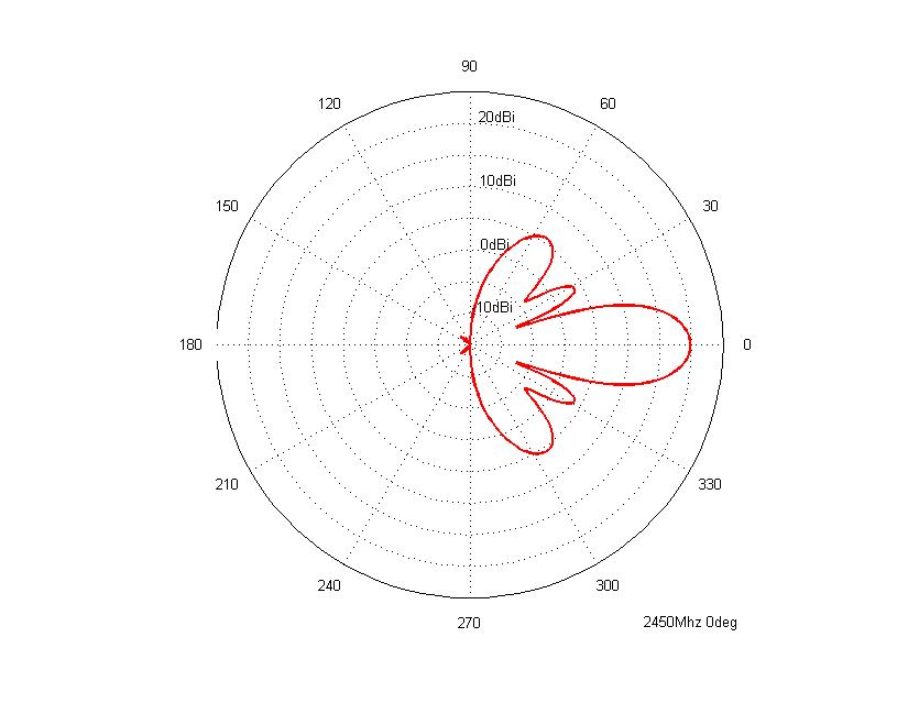
The radiation pattern for antennas is reproduced as lobes. The directivity of the antenna is determined by the width of the main lobe, and the immunity from interference is determined by the level of the side, rear.
A similar homemade outdoor antenna, known as a "horn" (fan vibrator), was often used to receive a TV broadcast signal not so long ago. According to the parameters, it would be suitable for the "numbers". But it is used only for receiving MV from the 1st to the 12th channel. By the same principle, you can make a UHF antenna.
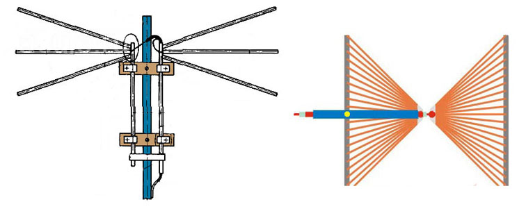
The simplest design is metal plates in the form of isosceles triangles. The triangles must be positioned so that their right angles are facing each other with a gap of about 1 cm. Two rails must be strengthened along the hypotenuses and copper wires (enamelled) of any diameter should be installed at a distance of 2-2.5 cm from each other. The width and height of the decimeter antenna are the same. When attaching the cable at a zero potential point, it can be tied without soldering.
If you stretch such an antenna in the area of \u200b\u200bthe window, one and a half meters wide, then it will receive a TV signal from any direction, without additional rotation. The disadvantage of the design is the low gain, and the CPD does zero. So in places with strong interference and a very weak signal, using an antenna is problematic.
Important. Sometimes radio amateurs try to make an omnidirectional antenna using a helix instead of a triangle, as it is smaller in size for similar frequencies. But it is more difficult to construct this type of UHF antenna with your own hands. Difficulties cause and coordination with the cable.
A kind of all-wave antenna, easy to manufacture, allowing you to get a decent image. Well suited for use in strong but intermittent signal environments. The device is a classical dipole circuit. With their dimensions, 0.5-liter aluminum cans are ideal for use as the arms of a vibrator in the UHF range. If you take banks of larger or smaller dimensions, then the reception frequencies will change. The principle is taken as a basis that with an increase in the diameter of the vibrator arms (linear), the operating frequency range expands while maintaining other characteristics.
The most simple antenna of two cans is suitable as a room for receiving an analog signal. The cable is not even subject to agreement with no more than two meters in length.

Sequencing:
- Attach a plug to connect to the TV at one end of the cable, strip the other by removing the insulating layer, 10 centimeters from the beginning. Unweave the cable cores, remove the foil;
- Attach the central core of the cable to one bank, and the wires of the shielding braid to the other;
- Using adhesive tape or electrical tape, install the cans on the insulating frame with the open part towards each other. It can be a wooden plank or a regular clothes hanger.
The distance between the banks is set approximately - 7-8 cm.
Important! It is necessary to ensure a tight fit of the wires to the metal of the can.
Cans can be assembled into a whole grid, with a mesh screen mounted on the back to enhance the protection against interference. This design is used outdoors, fixed on a dielectric mast. The screen must also be connected to the mast with dielectric materials. If you make more than 4 crossbars, then there will be difficulties in matching the cable, 2 - will not provide sufficient amplification. The distance between the crossbars is equal to half the average wavelength of the channels to which you want to tune reception. If there is an amplifier, it can be mounted additionally.
Another simple one. The goal is to get a circle-shaped frame capable of receiving a narrow range signal. Antenna for digital TV must have high protection against interference. This design is also a selective filter that reduces interference. It works well inside apartments with reinforced concrete walls.

The disadvantage of this antenna is that the input impedance of the frame will be about 300 ohms, and for the feeder 75 ohms - the characteristic impedance. It is necessary to install a matching device or make a frame with an input impedance of 75 ohms. It has the shape of a rectangle (the aspect ratio is 1:2). Both options are not very convenient. There is a third original solution - for a matching device, take the same cable, making a special loop out of it.
Based on the calculations, for the decimeter range for the ring, you need to take a piece of coaxial cable 5.3 m, for the loop - 1.75 m

Making a loop antenna:
- Cut off a piece of cable for the ring and for the loop;
- Part of the cable is bent into a ring and installed on plywood, plexiglass or other insulating material;
- A loop is made from another piece, the ends of which should be flush with the end of the cable heading to the TV or receiver. Can be fixed with tape
- The wires of the three shielding braids are connected to each other by soldering. The shield conductors from the loop must be connected on both sides to the shielding conductors of the ring. The central wire of the cable to the TV is on one side.
Note! The structure, placed outdoors, is protected from the weather by a plastic case.
wave channel
The maximum gain, gain, and interference protection for a self-made device is provided by the wave channel antenna. Suitable for use at a considerable distance from the broadcasting center. In the city it is able to reduce interference, as it has an accurate directionality. The same property limits the number of received channels, since outside the frequency selected for tuning, the characteristics of the antenna are sharply reduced.
Antenna drawings represent a device that consists of shortened directors, or guides with capacitance, an active vibrator and a reflector. The electromagnetic signal is oriented by the directors in the direction of the active vibrator. Behind him, a reflector of greater length with inductive resistance reflects the waves passing by to him.
Important! One reflector is enough, and there can be a different number of directors: up to 10 and more. With a large number directors increases the gain, but the range of received frequencies falls.

The TV cable is connected to an active vibrator. From its relationship with the directors and the reflector, its own wave resistance decreases. The strength of the fall depends on the gain. As a result, there is a mismatch with the television cable. For this reason, the active vibrator is made in the form of a loop, having an initial resistance of 300 ohms. After interacting with several directors and a reflector, the resistance becomes 75 ohms. This ratio is valid for a five-element device.
For UHF, vibrators must be made from a metal tube from 6 to 10 mm in diameter. Total elements of the decimeter device 16. All elements are connected with the boom in fact at points with zero potential. This means that the material of the boom, as well as the mast, can be taken any. For example, pipes made of polypropylene.
Important! The antenna must be strictly matched to the cable. A loop of coaxial cable can be used as a matching device.
In theory, the length of the loop is half the wave length (the wave is taken as a working one). But it is necessary to take into account the correction for cable insulation. When using a 75 ohm coaxial cable, the loop size will be 0.35 times the wavelength. Inter-terminal distance - 6 cm.
Zigzag
Zigzag is a Kharchenko antenna scheme, refers to broadband devices. The design dimensions for the decimeter range are compact and easily allow it to be used indoors. It is especially effective in remote settlements when receiving in various directions. The limits of the received frequencies with the preservation of the parameters overlap with a factor of 2.6-2.7.
The classic zigzag is difficult to manufacture and requires precise calculations. Widely used for receiving analog TV programs. For digital signal everything is greatly simplified.
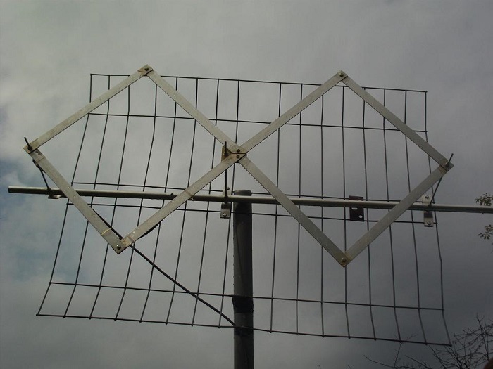
Rhombus
The rhombus design is a kind of zigzag. The best material for the main circuit is copper tubes, another possible is aluminum sheets (thickness 6 mm and above), cut into strips. In order to create a container, inserts made of tin, metal mesh or foil are used within the boundaries of small side rhombuses. Behind the reflector is strengthened. Capacitive inserts and a reflector complete the structure to increase sensitivity. With a good signal, these elements can be dispensed with.
Important! Mesh or tin inserts are soldered along the contour. When using sheets of thin metal, this is not necessary.
The coaxial cable should not be bent strongly. It is brought to the side top of the rhombus, and then goes to the center and soldered.
At the point with zero potential (lower apex of the rhombus), an electrical connection must be made to the wires of the shielding braid.
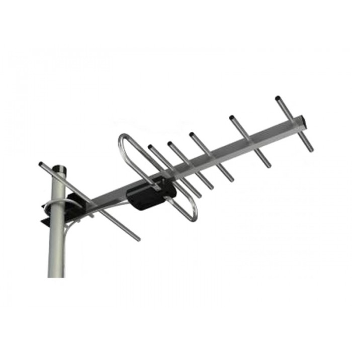
log-periodic
If the antenna does not always cope with an analog signal without adjustment, then it is ideal for receiving a digital television signal. It consists of a long rod to which are attached halves of dipoles of different lengths. The gaps between the vibrators and their length vary exponentially. Calculating the antenna is quite difficult. There are several methods presented on the Internet.

Features of a log-periodic antenna:
- The central rod feeds the right and left vibrators separately. They must be in antiphase;
- The rod consists of two carriers. Left-right vibrators alternate carriers in turn. The first left is the top carrier, the first right is the bottom. The next row is the opposite;
- The number of vibrators is determined by the design of the antenna. The most extended, located behind, are equal in length to the length of a half-wave of the lower limit of the range;
- The coaxial cable is laid to the middle of the structure, passing inside one of the guides. At the outlet of the nose, the central core must be connected to the second carrier. Such a line, consisting of two wires, will act as a balancing transformer. There is another option for laying;
- For better matching, the line is shorted behind the longest vibrator (distance 1/8 of the wavelength of the lower limit of the range);
- The diameter of the tubes must be taken 10-15 mm for a decimeter wave.
- Thin cables will cause a lot of attenuation and require wire at least 6mm in diameter. The cable is tied only from the inside, otherwise the quality of the antenna drops.

- All structural elements with flowing signal current must be soldered or welded. This is especially true for street antennas;
- Coaxial cables do not work well with conventional soldering, and prolonged heating can damage the cable. It is best to solder using low-melting solder, replace rosin with flux paste.
There are simpler ways to make homemade antennas and more complex. Depending on the knowledge and experience gained, each user can choose an option that is acceptable to him personally.
Video
Which antenna to choose for digital television? How are antennas different? How to apply power to an active antenna? Which antenna is best? These and other questions on the site
Hello! By occupation, I have to deal very closely with connecting and configuring antennas for digital terrestrial television.
Therefore, based on the experience gained, I have the opportunity to share how to choose an antenna for digital television and set up dvb-t2 - free 20 channels.
Quick article navigation
Which antenna is suitable for DVB-T2 digital television
With the advent of digital terrestrial television, many people have questions related to choosing an antenna for DVB-T2. For example!
- Can I use my old antenna, if there was one?
- Is an antenna of the "Grid" type suitable for this, it is also "Polish"
- Do I need an antenna with or without an amplifier?
- if there is a question about purchasing a new one?
- Do I need the advertised antenna "Key to Free TV"
Let's first understand what antennas are in general.
To receive television signals, antennas of the meter (MV) and decimeter (UHF) ranges are used. There are broadband antennas, this is a “hybrid” when elements of the MV and UHF bands are used in the design of the antenna.
These antennas are easy to distinguish from each other by size.
In the MW range, the elements are longer. Everything according to the name.
So in MW antennas, elements are approximately from half a meter to one and a half meters in length.
And the elements of the UHF antenna, in length, are only about 15 to 40 cm.
It is the UHF antenna that is needed for digital terrestrial television.
 Antenna meter band (MV)
  An example of a UHF antenna (UHF)
  Broadband antenna, MV and UHF bands.
  Antenna type "grid"
  Broadband antenna "Hummingbird"
 So - To receive digital terrestrial television, you need a decimeter antenna, i.e. antenna with short elements. Or broadband.
Now you can evaluate whether your old antenna is suitable for receiving television in the DVB-T2 format. The only question that remains open is its serviceability and efficiency in your area.
In addition to dividing by received bands, antennas are also divided into ...
Indoor and outdoor (External) - I think everything is clear with the application.
And also active and passive - more on that later.
Well, brief digression in a difficult topic of terrestrial antennas carried out. Let's continue...
Features of the distribution of a television signal
The distance over which a signal is transmitted in the UHF range does not differ in a large coverage area. It is much less than in the meter range.
For example:
If you used a radio, you may have noticed that you will not be able to catch distant foreign radio stations in the FM or VHF bands, but only those nearby, local ones.
But on the other hand, you can catch a whole bunch of foreign ones in the NE or HF bands.
This is because medium and short waves, like meter waves, propagate over long distances, and ultrashort waves, like UHF, over short ones.
This disadvantage of the UHF range for digital TV is compensated by the location and number of television transmitters - by analogy with towers cellular communication, a lot of them.
Also keep in mind that the TV signal is perfectly reflected from the objects encountered on the way.
This allows you to receive transmissions when it is not possible to direct the antenna towards the TV tower. Or there are obstacles to the direct passage of the signal.
Look around! Is it possible to receive a reflected signal?
So with the right choice of antenna and its correct installation you will surely succeed.

What else to consider when choosing an antenna
Conditions for receiving a television signal are very different in different places and these conditions must be taken into account when choosing an antenna.
Here are some factors that determine which antenna you need to purchase and how to install.
- TV transmitter power and
- The terrain is mountains, lowlands, plains.
- Standing nearby and blocking the antenna in the direction of the tower, tall, dense trees.
- High-rise buildings and your location in relation to these buildings and the tower.
- The floor on which you live - the higher, the easier it is to need an antenna.
- The ability or inability to turn the antenna towards the transmitting tower.
Active and passive antennas - what's the difference?
Antennas of any kind can be either active or passive.
Passive antennas are those that amplify the signal only due to their design, without the use of electronic amplifiers, such antennas are used in areas with a strong signal.
Active antenna - in its design it has an amplifier, such an antenna needs to be connected to a power source.
The amplifier helps to raise the level of the received signal in areas of uncertain reception.
How to connect power to an active antenna amplifier, several ways
Antenna amplifiers are powered by 12 or 5 volts. But in recent times Increasingly, manufacturers are focusing on the production of antennas with a five-volt supply.
And there is a reason for this! Such antennas are easier to connect for those who use a set-top box for DVB-T2.
Three ways to connect
A) Use a special power supply with a separator that produces a voltage corresponding to your amplifier.
The purpose of a separator is to separate. It passes voltage to the antenna, but does not pass it to the TV jack. However, this does not interfere with the signal from the antenna amplifier entering the TV.
B) If a DVB-T2 prefix is used. A voltage of 5 volts can be applied directly from the console. And for any amplifiers and 5 and 12 volts.
This does not require any additional wire, power supply, etc. A voltage of 5 volts, from the antenna jack of the set-top box, directly through the antenna cable, will go to the amplifier.
You just need to turn on this power directly from the set-top box menu. Go to the settings section and find the item “Antenna power ON-OFF”, select ON, and exit the menu (the names of these items may differ in different models of set-top boxes)
C) If you have an LCD TV with an already built-in DVB-T2 tuner, then in addition to the method under the letter A), you can do the following.
You will have to purchase a special adapter to power the amplifier from any USB port, first of all, the USB port of the LCD TV itself is considered. But you can connect to any charger with a USB output.

Which antenna to choose - consider examples
As you understand from all of the above, when choosing an antenna for yourself, you need to evaluate various factors.
A few examples:
Distance to tower 5-15 km
You live in a city where there is a DVB-T2 signal transmitter. Or in locality, close to 5-15 km from the transmitter.
Most likely, an indoor antenna is suitable for you, even the simplest one. Especially if you live above the first floor.
And being not far from the tower, even a simple piece of wire instead of an antenna can be enough.
Given the prevalence of towers and quite a large number of places with a strong signal, scammers use this, offering various, in fact
Under the conditions described above, they will work well.
But keep in mind, the number of channels will be no more than what the TV tower broadcasts in your area! But not 100 or 200 as advertised.
Therefore, the question arises, is it necessary to pay off several hundred, or even thousands, for an ordinary indoor antenna from advertising ?!
Here are some low cost, compact antenna options for areas where there is a good signal.
 Indoor antenna for locations close to the tower.
  Indoor antenna for locations close to the tower. Another option
  This variant may work in slightly more difficult conditions than the previous two, especially the amplifying version.
 Indoor antenna - application features
The correct place for an indoor antenna is not where it will look good and stand comfortably, this is where it will receive a good signal. And these two circumstances - "to look" and "to accept" do not always coincide.
Because often the best, and sometimes the only place where you can catch a signal, is a place near the window overlooking the TV tower. Take this into account!
To solve this problem, you can add a cable of the desired length and for some antennas (for example, those in the photo above) this is not difficult.
But there are indoor antennas that have a built-in power supply in their housing. They also have a power cord for connecting to an outlet. And of course the cable to connect to the TV.

This may seem convenient, but alas, this is not always the case.
Often, the place where the antenna is able to receive a TV signal is not at all near the TV and the outlet, but for example, by the window.
And in this case, a short power cord will become an obstacle to placing the antenna in the right place. In addition to the cable, you will also have to pull the extension cord. In general, a bunch of wires.
You live at a distance of about 25-30 km or more from the TV tower.
Of course, much depends on the power of the transmitter.
But in general, at a distance of 25 km, a small outdoor antenna is sufficient. For example, those that are depicted at the very beginning of this post mean the UHF antenna or the broadband Hummingbird.
In my area, from a distance of 25 km in direct line of sight, a passive UHF antenna with an arrow length of about 80 cm has a confident reception without the need to raise the antenna above two meters from the ground.
You can also receive a good active, indoor antenna.
In some houses, even from the first floor, if there is a window towards the tower or the ability to receive the reflected signal from neighboring buildings.
Floor above the second significantly increases the likelihood of success.
There is a simple principle of how to determine the power of an antenna - the longer the antenna boom, the greater the coefficient of its own gain, and not due to the amplifier.
Antenna for difficult signal reception conditions
For example, an active antenna, the photo of which is below, in our area draws a signal from a distance of 60 km or more. It is successfully used in the most difficult places, in houses located in a strong lowland, its length is about 1.7 meters, but there are antennas under 4 meters in length.
 In addition to the length, in difficult conditions or at a great distance from the TV tower, the presence of an amplifier plays an important role, i.e. antenna must be active.
There are options for powerful antennas, where instead of one boom, three are used at once, so the ability of the antenna to amplify the signal due to the design alone increases greatly.
And in tandem with an amplifier, this antenna becomes a very powerful trap for a television signal.

But impressed by this antenna, do not rush to run after it. It is needed only under really very, very difficult reception conditions.
In most cases, other, much cheaper options are sufficient. In addition, if the signal is already so strong in your area, then the amplifier in the antenna will only interfere.
Here is just the case when porridge can be spoiled with butter. An example of this is described below.
Polish antenna array for digital television
In some cases, the "Grid" antenna can work quite successfully when receiving digital television. Especially if you are not very close to the transmitting tower.
More than once, however, I came across a situation when, using their old antenna - the Pole (Grid), people could not get a digital broadcast signal from it.
Either in general, or the signal periodically "fell off" the picture fell into cubes, there was a freeze in the image and sound. One of the digital television packages could disappear, while the other worked fine.
The problem with these phenomena is the overamplification of the signal.
There is a way out, consider the options ....
1) Sometimes it's just enough to unplug the antenna's power supply from the outlet and that's it. But this does not always help, and then more serious measures are needed.
2) Reduce the power supply voltage of the amplifier using an adjustable power supply. Or supply power directly from the set-top box, bypassing the separator of the standard antenna power supply, by installing a regular plug.
3) Get to the amplifier board, the scarf that is on the antenna itself, and connect everything without an amplifier.
4) Throw away this old dilapidated antenna and buy a normal, UHF band.
P.S. New, grating type.
I hope this article will be useful to someone, leave your feedback, comments, share your experience.
P.S. If you are purchasing a new antenna and are not sure if it will suit you, ask your local antenna vendors.
Sometimes they are well aware of which antenna is better to take based on your place of residence.
And agree on the possibility, if it suddenly does not fit, change to a different type of antenna. At least in my shop it is possible.
Digital terrestrial television (DVB-Digital Video Broadcasting) is a technology for transmitting television images and sound using digital coding of video and sound. Digital encoding, unlike analog, provides signal delivery with minimal losses, since the signal is not affected by external interference. At the time of writing, 20 digital channels are available, in the future this number should increase. This number of digital channels is not available in all regions, learn more about the ability to catch digital channels you can visit www.rtrs.rf. If there are digital channels in your area, in this case, it remains to make sure that your TV supports DVB-T2 technology (this can be found in the documentation for the TV) or buy a DVB-T2 set-top box and connect the antenna. The question arises - What antenna to use for digital TV? or How to make an antenna for digital television? In this article, I would like to dwell in more detail on antennas for viewing digital television, and in particular, I will show how to make a digital tv antenna.
The first thing I would like to emphasize is that digital television does not need a specialized antenna, an analog antenna is quite suitable (the one you used earlier to watch analog channels). Moreover, only a television cable can be used as an antenna ...
In my opinion, the simplest antenna for digital television is a television cable. Everything is extremely simple, a coaxial cable is taken, an F connector and an adapter for connecting to a TV are put on one end, and the central core of the cable (a kind of whip antenna) is exposed at the other end. It remains only to decide how many centimeters to expose the central core, since the quality of reception of digital channels depends on this. To do this, you need to understand at what frequency digital channels broadcast in your region, to do this, go to the website www.rtrs.rf/when/ here on the map, find the tower closest to you and see how often digital channels broadcast.
More detailed information you will get if you click the "More Info" button.

Now we need to calculate the wavelength. The formula is very simple:
where, λ (lamda) - wavelength,
c - speed of light (3-10 8 m/s)
F - frequency in hertz
or easier λ=300/F (MHz)
In my case, the frequency is used 602 MHz and 610 MHz, for the calculation I will use the frequency 602 MHz
Total: 300/602 ≈ 0.5 m = 50 cm.
Leaving half a meter of the central core of a coaxial cable is not beautiful and inconvenient, so I will leave half, maybe a quarter of the wavelength.
l=λ*k/2
where l is the length of the antenna (central core)
λ- wavelength (calculated earlier)
k - shortening coefficient, since the length of the entire cable will not be large, this value can be considered equal to 1.
As a result, l=50/2=25 cm.
From these calculations, it turned out that for a frequency of 602 MHz, I need to strip 25 cm of coaxial cable.
Here is the result of the work done

Here is what the antenna looks like when installed.

View of the antenna while watching TV.

In the AMV range, due to a decrease in the effective length of the receiving antenna, with increasing frequency, a lower voltage develops at the antenna input than under the same conditions in the meter range. Therefore, it becomes necessary to install antennas with a high gain. In antennas of the "Wave channel" type, this is achieved by increasing the number of directors, creating in-phase arrays from multi-element antennas (Fig. 10.30). Since the dimensions of the antenna elements of adjacent channels differ slightly, they are usually given for a group of channels (Table 10.20).
Table 10.20

13-element antenna type "Wave channel" consists of three reflectors, an active loop vibrator and 9 directors. The distance between the ends of the loop vibrator A is 10...20 mm. The diameter of the antenna vibrators is 4...8 mm. The antenna gain is 11.5 dB, the opening angle of the main lobe of the radiation pattern in the horizontal and vertical planes is 40°.
19-element wave channel antenna for the UHF range (Fig. 10.31) consists of three reflectors, an active loop vibrator and 15 directors. The vibrators are made of wire and tubes with a diameter of 4 mm. They are attached in any way to the carrier boom with a diameter of 20 mm. The boom length for any channel group is 2145 mm (Table 10.21). The antenna gain is 14...15 dB, the opening angle of the main lobe of the radiation pattern in the horizontal and vertical planes is 30...32.
Broadband antenna of the "Wave channel" type for reception in channels 21 ... 41(Fig. 10.32).
Depending on the distance to the television transmitter and the zone of reliable reception of its signals, the number of elements (directors) of the antenna can be reduced to 8.11 or 15.
In the case when preference is given to reception in one television channel (for example, reception of an NTV program from Kolodishchi), the dimensions of the antenna elements and the distances between them can be recalculated for this channel.

Table 10.21

The UHF broadband antenna has the highest gain (13 dB) in the 28th channel, the average frequency of which is 500 MHz. The conversion factor (Kp) in this case is determined by the formula


where fcp is the average frequency of the UHF channel, MHz. For the 37th channel, the average frequency of which is 562 MHz, Kp is equal to:
Kp=530/562=0.943.
Multiplying the dimensions of the elements and the distance between them by 0.943, we obtain the dimensions of the antenna for the 37th channel (Fig. 10.33). You can also recalculate a broadband antenna for any channel (or group of channels) of the UHF. The average frequency of the channel (group of channels) is given in Table. 10.2, the length of the half-wave loop - in table. 10.1. When using a metal carrier boom (traverse), the dimensions of the elements obtained during recalculation are increased by half of its diameter.
The gain of the channel antenna increases to 14...15 dB. An antenna of eight elements is used at a distance of up to 20 ... 30 km from the village. Kolodishchi, from 11 - up to 30 ... 40, from 15 elements - up to 50 ... 60 km. Behind the zone of reliable reception at a distance of up to 70 ... 90 km, an antenna of 24 elements is used. To ensure good quality of the received image, an antenna amplifier is installed directly on the mast.
The antenna is little influenced by nearby objects and has good repeatability. Deviations of up to 2 mm from the calculated dimensions are permissible with virtually no deterioration in the antenna parameters.
Antenna type "Wave channel" with a complex passive reflector(Fig. 10.34; tables 10.22 ... 10.24) consists of a lattice reflector (Fig. 10.35, a), two sheets of which are installed at an angle of 90 ° at the end of the carrying boom, an active loop vibrator (Fig. 10.35, b) and 18 directors.

At the same time, the first two directors (A1 and D2) are two-story and spaced vertically by the thickness of the carrier boom (Table 10.23).
Table 10.22


The main advantage of such an antenna is the reliable screening of the rear hemisphere due to an increase in the coefficient of protection when installing a complex reflector. The latter concentrates the energy of the useful signal in the direction of the active vibrator, which helps to increase the gain of the antenna.
Table 10.23

Table 10.24


On fig. 10.36 shows a side view of the antenna described above. A 6-element antenna is designed for short-range reception at a distance of up to 10...15 km from a television transmitter: 10-element - 15...25; 15-element - 25...40; 20-element - at a distance of 40 ... 60 km or more.
In the UHF range are widely used loop Antenna Triple Square, the frames of which are made of a single piece of copper, brass wire with a diameter of 2 ... 3 mm. With the dimensions of the decimeter range (Table 10.25), the antenna has sufficient rigidity. The wire must be bent in a certain way (Fig. 10.37). At points A, B and C, the wires must be stripped and soldered. In this design, instead of a stub (see Fig. 10.12) made from a piece of coaxial cable, a quarter-wave short-circuited bridge (see Fig. 10.11) of the same length as the stub (see Table 10.5) is used. The distance between the bridge wires remains the same (30 mm). The design of such an antenna is quite rigid, and the lower boom is not needed here. -

The feeder is tied to the right wire of the bridge from the outside. When the feeder approaches the vibrator frame, the cable braid is soldered to point X "the central conductor is to point X. The left wire of the bridge is fixed on a dielectric stand or, in the case of an external antenna, on a mast. It is important that there is no feeder and mast stand in the space between the wires of the bridge .
In the presence of copper, brass or aluminum strips, you can make diamond-shaped antenna(Fig. 10.38). The strips (1) are overlapped with screws and nuts. There must be reliable electrical contact at the point of contact between the plates. The thickness of the strips is arbitrary.
A diamond-shaped antenna can operate in the frequency band of channels 21 ... 60, its gain is 6 ... 8 dB. To increase it, the antenna can be equipped with a reflector (Fig. 10.39).
The simplest reflector is a flat screen made of tubes or pieces of thick wire. The diameter of the reflector elements is not critical (3...10 mm). The reflector sheet (2) is fastened with the help of supports (3) to a metal or wooden mast (4). Points 0 have zero potential, relative to the ground, so the posts (2) can be metal.
Table 10.25


Feeder (5) - a PK type cable with a wave impedance of 75 Ohm is laid to power points A and B. The cable braid is soldered to point B, and the central conductor to point A. At long-range reception, the diamond-shaped antenna can be equipped with a broadband amplifier (6).
2-element Swiss antenna(see Fig. 10.21) can also be used in the UHF range (Table 10.26).
Table 10.26