Accessories, inexpensive analogues and other devices available (3). Accessories, cheap analogues and other devices available(3) Problems with tes 12 3 nt
 A.L. Butov, p. Kurba, Yaroslavl region
At present, it is difficult to find a radio amateur who, once in his life, has not tried to assemble at least a simple low-frequency power amplifier. Making even a simple amplifier from a “blank sheet” inevitably takes a lot of time, and much of the time is spent not on assembling the amplifying module, but on various side work, for example, manufacturing a case, front panel, winding a transformer. Therefore, in order to reduce the time spent on the manufacture of a finished structure, it is possible to actually use ready-made assemblies and components, which will dramatically reduce the hours spent on assembly. As a result, taking into account direct and indirect costs, a home-made design will cost a little more than a similar serial one, and if you had to buy a minimum of components at retail prices, it may even be cheaper.

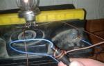
Once, a Bulgarian power supply, called the “Stabilized Current Rectifier TES-12-3-NT”, manufactured in 1985, underwent a trepanation. This device was assembled in a chic all-metal duralumin case measuring 240x210x55 mm with thick walls (see photo), which says "12V - FOR". Previously, this device was used to power the radio station, after the collapse of the USSR, our agriculture did not need radio stations, and this power supply continued to serve as an energy source for a simple Chinese radio tape recorder “voicing a personal plot. The Chinese radio tape recorder suffered from fever, chronic bronchitis, memory loss and a weak voice, which is why its symbiosis with the power supply shown in the photo had to be broken. And so that an amateur gardener would not be left in the garden and in the pool without music and news, it was decided to install a home-made audio power amplifier and a VHF radio receiver in the durable stainless steel case of this power supply.
A boring search in directories and price lists for a UMZCH chip suitable for this power supply led to an inexpensive TDA1521 type chip designed to build middle-class amplifiers. The microcircuit has built-in protection against a "click", thermal protection and protection against short circuits in the load circuit. The microcircuit provides an output power of 2x12... 15 W at a load of 4...8 ohms. Its minimum supply voltage is 15 V (unipolar), the maximum is 42 V. When the supply voltage drops below 15 V, the operation of the microcircuit is blocked. The TDA1521 chip is capable of operating both in dual-channel mode and in single-channel bridged mode, it can be powered by both unipolar and bipolar supply voltages. In the stereo amplifier, assembled according to the scheme of Fig. 1, a unipolar power supply is used. 
Unipolar power supply requires the presence of high-capacity oxide capacitors at the outputs of the amplifier for a relatively large operating voltage. About 20 years ago, such capacitors were also famous for their large dimensions, at present, the dimensions of oxide capacitors with a capacity of 2000 microfarads or more have decreased several times, and their cost is almost symbolic. The presence of separating capacitors at the output of the UMZCH allows you to avoid damage to the acoustic systems in the event of a failure of the UMZCH microcircuit, as well as biasing the speakers with a zero bias current, which worsens the sound. The amplifier is assembled according to a scheme close to a typical one. The resistor R3 controls the volume, the switch SB1 can switch the operating mode of the device. In one mode, the input of the amplifier will be connected to the radio receiver built into the PSU case, in the other - to an external signal source. The voltage gain of the microcircuit is about 30. There is no stereo channel balance control and tone controls in the amplifier due to the lack of need for this and as UMZCH components outdated 15 years ago. It is no longer the 60s ... 80s of the last century, when the wear of a cheap, short-lived magnetic head of an audio tape recorder was compensated by twisting the tone control knobs all the way. 
Figure 2 shows a block diagram of the TDA1521 integrated circuit. The 12 V voltage regulator present in the TES-12-3-NT power supply had to be eliminated, since it stabilized the “minus” and not the “plus”, as desired. If desired, a stabilizer with a common "minus" can be assembled on any suitable integrated circuit. From the cunning Bulgarian product, a case, a power transformer T1, rectifier diodes VD1, VD2, capacitors C9-C13, an LED and a SA1 power switch were left. The power supply assembly has been redesigned as shown in Figure 3. 
Also in this figure you can see the +3.2 V voltage regulator for powering the radio receiver module and how this radio receiver module is connected. As this module, a tuned board from a primitive pocket Chinese radio receiver with auto-search for radio stations was used. Tuning to the radio station is done using two buttons, the sensitivity is very high, the sound quality is relatively mediocre, inferior to the sound of neatly and competently assembled home-made radios on the well-known K174XA34 chip. Such radios were popular in the second half of the 1990s and early 2000s. Since the author did not want to assemble another radio receiver, after explaining to the owner of the power supply what was required of him, he brought a Chinese toy without much thought, the board from which eventually settled next to the makeshift amplifier.
A photo of the appearance of what happened as a result is shown in Fig. 4.

The amplifier board is located on the left in the photo, the voltage rectifier and +3.2 V stabilizer boards are in the middle, the power transformer is at the top right, the radio receiver module is at the bottom right. To tune into the radio stations, two buttons with freely open contacts made on the basis of microswitches are connected in parallel with the regular membrane buttons of the radio receiver. The wires from the radio board to these buttons should be as short as possible.
Details:
Instead of a TDA1521 type chip, you can install TDA1521Q. The TDA1521A chip is not suitable for working in this design. The microcircuit must be installed on a heat sink, which can be used as a metal case of the structure. A thin mica insulating gasket must be installed between the microcircuit and the metal case. The microcircuit is pressed against the heat sink with the help of two MOH screws and a metal plate. Between the microcircuit case and the pressure plate, it is necessary to install a thin gasket made of thick electric cardboard, which will prevent deformation and damage to the microcircuit case. When installing a microcircuit on a heat sink, heat-conducting paste is used.
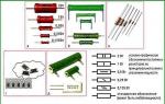
Instead of the KT815V transistor, you can use any of the KT815, KT817, KT805 series. Zener diode KS139A can be replaced by KS407B, KS139G, 2S139A, 1N4730A, BZX/BZV55C-3V9. Instead of a KD521A diode, any low-power one is suitable, for example, 1M4148, KD522A. Bulgarian diodes KD2002 can be replaced by any of the series KD213, KD206, KD242, R600. Oxide capacitors - imported analogues of K50-35, non-polar - any ceramic or film, designed for an operating voltage of less than 63 V. Capacitors C6.C7 in the amplifier circuit are installed near the power leads of the DA1 microcircuit. The variable resistor was installed dual type SPZ-Z0a. The common wire is connected to the metal case at one point, preferably close to this resistor. The noise suppression choke L4 contains 6 turns of a multicore installation wire folded in half, it can be wound on a ring with a diameter of 16 ... 24 mm from any low-frequency ferrite. Inductors L1, L2 can be wound on the same ferrite rings, contain 2 turns of a double-folded mounting wire. Choke L3 contains 24 turns of PEV-2-0.43 wire wound on a cardboard mandrel with a diameter of 3 mm. You can use any suitable transformer T1, rated for a load current of at least 3 A. When using a full-wave rectifier circuit, the voltage on each secondary winding must be 18 ... 22 V. When building a rectifier in a bridge circuit, one such winding is sufficient. Fuse FU1 is a regular fuse, FU2 is a self-recovering fuse of any type for a current of 3 ... 4 A.
Working with the device
During prolonged operation of the amplifier at maximum power, its metal case-heat sink almost does not heat up. If your design of the "garden" amplifier will be approximately the same, and you prefer music to the lively chirping of birds and the barking of rural dogs, do not expose the amplifier to direct sunlight on a hot summer day, otherwise the design may suffer heat stroke and premature death associated with it.
The quality of the amplifier, assembled on a two-channel TDA1521 chip, is comparable to similar amplifiers assembled on the somewhat undeservedly popular TDA2030. Undeservedly, because for a long time there have been microcircuits with similar switching circuits that surpass this microcircuit in the main parameters, for example, TDA2051H. If you decide to partially or completely repeat this design, then you should not focus specifically on the TDA1521 chip. It is likely that in your area for the task at hand and under the existing or under the newly assembled power supply at an affordable price, there are microcircuits with the best parameters.
It took 22 man-hours and about 9 USD to create this design. This amount includes: the cost of the microcircuit, oxide capacitors and a self-resetting fuse. All other parts were used from dismantled old, shareware equipment. The cost of solder, rosin, coffee drunk and $ 0.2 per 4 kWh of electricity consumed during the assembly of the device are not taken into account. With a typical cost of male wage labor in our area of about 5-7 USD per hour, we find that the creation of the structure cost, as it were, at least 125 USD. Against this background, if every hour of your life is expensive, it is more expedient and profitable to go to a store and buy a ready-made amplifier with real 2x10...15 W output power, small speakers and a remote control for 125 USD.
In conclusion, according to the author, it is not worth spending hundreds and thousands of hours to create "the best amplifier in the world." It is much more important what you listen to, with whom you listen, what performers, what composers, and not how and on what one-day “hits” are listened to.
RA 10*2008
This text was written not so much for the sake of reviewing the power supply board itself, respected Kirich and other authors succeeded in this, but rather for the sake of describing the design I got as a whole, with the additions that, in my opinion, are necessary for this power supply in the form of a fan thermal controller, an indicator voltage and current, automatic switch of transformer windings, electronic load disconnection, and of the power transformer itself and the housing. Some of the devices were bought on AliExpress, and the other part was assembled from scratch. For the former there will be links, and for the latter there will be diagrams ...
So the components used are:  - 150W, having 2 windings of 12 volts, bought in a chip and a dip. Such a transformer was chosen with the calculation of the possibility of switching windings, dividing the output voltage range into 2 sub-ranges - 0-11V and everything above (using either one 12-volt winding or 2 series-connected same windings, giving ~ 24V in total). Over the two factory secondary windings, 2 additional ones were still wound. The first is low-power at 13V to power additional devices and a cooling fan. The second winding is more powerful, at 7V., wound with 1.5mm wire (it could have been thinner, but I had one available), to power a separate 5-volt USB output connected to a 7805 linear regulator;
 - laboratory power supply from AliExpress. The set really began to cost a penny - a little more than $ 5. Flew to Minsk in 29 days, the track was tracked. The board I assembled is in the photo above. I replaced only the complete conder for 10,000 microfarads and rectifier diodes, for a current of 5A. Change operational amplifiers until it becomes ...;
 - with a temperature indicator and a remote temperature sensor also from AliExpress.
The temperature controller, worth $ 1.65, reached Minsk in 22 days, the track was lying down. Excellent device, I must say. It can work in one of two modes - cooling or heating. That is, depending on the selected mode, the thermal controller controls either the heater (turns on if the temperature drops below the set one) or the fan (turns on if the temperature exceeds the set one). A hysteresis value is set to turn off the fan or heater. The controller is controlled by 3 buttons, the values are displayed on a 3-character indicator. There are detailed instructions on the seller's page.
Instruction

 - voltage and current from AliExpress. Price $3.94. The order went for 5 weeks, the track was not tracked. It should be noted that the indicator turned out to be quite suitable, we will test it later;
 - Homemade transformer winding switching unit (found on the Internet). This is perhaps the most important addition to a linear regulated power supply. The fact is that the efficiency of such sources is not very high, especially at low output voltages. So, for example, with an output voltage of 5V and a current of, say, 3A, about 75W should be dissipated at the output transistor. And in this mode, when the PSU is powered by 24 volts AC (2 windings of 12 volts each), the cooling fan controlled by the thermal controller almost never turns off. And with an input voltage of ~ 12V, on the contrary, it turns on very rarely and for a short time. Thus, this addition allows you to significantly improve the operating modes of the power supply, especially when you consider that I mainly use voltages up to 12V. The only thing is that the solution I chose is not the best, because, when the voltage decreases, at the moment of switching the windings from two to one (from 24v to 12v), there is a short dip in the output voltage. The triac circuit is devoid of such a disadvantage. And for myself, I decided that this nuance is not fundamental to me.
  The device was assembled on a breadboard, a rectifier and a 12V voltage regulator were immediately placed, from which the relay, thermal controller and fan are powered. For this stabilizer, an additional low-power winding was wound on the transformer;
 - And this is a completely self-made block of electronic load connection, about it in more detail:
So, a small TK.
After turning on the power supply, the load must be disconnected, regardless of the last state.
- A flashing red LED should indicate that the load has been switched off.
- The connected load must be indicated by a permanently lit green LED.
- The load is connected by means of a relay.
- Hardware suppression of contact bounce.
 Circuit corrected, thanks to users IIIap, varicap and alexky who noticed it (wrong polarity of the protection diode). The circuit is based on a cheap Atmel ATtiny2313 microcontroller and a 74HC14 Schmitt trigger.
The circuit is powered by 12 volts, necessary for the operation of the relay. A 7805 linear converter was used to power the microcircuits.
After switching on, the red LED VD2 flashes. Schmitt trigger 74HC11 allows you to finally and irrevocably get rid of contact bounce. When the button is pressed, the VD2 LED goes out, and VD1 (green) lights up, simultaneously with it, the transistor VT1 opens and the relay K1 turns on. The next time you press the load and the green LED VD1 are turned off, the red LED VD2 starts flashing. Diode VD1 protects the transistor from voltage surges on the relay coil. The circuit is assembled on a breadboard. If you do not put a Schmitt trigger at the input (and deal with bounce by software), then a 10K pull-up resistor is needed at pin 7 of the microcontroller. The plans are to add one more control channel to the microcontroller int0 input. The USB output will be controlled.
The control program is written in the Bascom environment.
In the main cycle, the red LED flashes, provided that the PB2 output is low, i.e. the load is off and the green LED is off. On interrupt Int1, the Swbutton subroutine is called. The Toggle operator switches the states of the PB2 output (if it was 1, it will become 0 and vice versa). After switching the output, the program returns to the main loop, until the next interrupt;
Under the spoiler source
$regfile = "attiny2313.dat"
$crystal = 4000000
Config Portb.1 = Output
Config Portb.2 = Output
Config Pind.3 = INPUT
Config Int1 = Falling
Dim Wtime As Byte
On Int1 Swbutton
Enable Interrupts
Enable Int1
Do
if pinb.2 = 0 Then
Set Portb.1
Waitms Wtime
Reset Portb.1
Waitms Wtime
Else
'Pinb.4 = 0
End if
loop
End
swbutton:
Toggle Portb.2
 - Relay. On the left, a relay in a blue case is used to turn on / off the load, and a relay in a transparent case, the first group of contacts switches the transformer windings, and the second group turns on the LED indicating the connection of the second winding;
 - And finally, the finished case from the old tape streamer. DDS cartridges for 2Gb are no longer relevant for a very long time, so the device was mercilessly dismantled for spare parts. A case with a native fan is perfect for my power supply;
 Here is the front panel. Temporary, because I will redo both the layout and the material of the insert to be changed (there was white foamed plastic - it looks clumsy, but there will be a plug from the computer case, which falls into the color of the entire device). But this is a little later, when they reach from China. A USB connector will also be added. Red regulator - voltage, blue - current (the colors of the knobs are selected in accordance with the colors of the glow of the indicator segments). The rectangular green LED under the indicator lights up when the second winding of the transformer is connected. Above the blue regulator is a current stabilization indication LED (red). Well, in the area of \u200b\u200bthe output terminals, there is a red button for connecting the load and a two-color LED (red-green).
  Everything is made on the connectors - the front panel is completely removable. The output of the power supply unit is connected to the front panel using a Deans type connector, which is used for batteries of remotely controlled models;
All components are interconnected according to the following scheme (corrected, thanks to user MisHel64):  A little assembly:
  The winding switch and load disconnect units are assembled in a sandwich and installed near the front panel. A load disconnect relay and a fan thermal controller board are installed nearby.
 On the inside, a heatsink is screwed to the case fan (from some old processor). A transistor and a temperature controller sensor are screwed to the heatsink with thermal paste. Everything is installed in the case from the back side.
 The main board is installed on high racks with the parts down. Such an arrangement, although not the most heat-efficient, can not be placed in another way the board and the transformer in this case.
 I decided to connect the transformer windings using Wago terminals, it turned out very convenient. There is a slight confusion in the wires, although they were stacked and pulled together with ties. Maybe I'll change it later...
  And the last component is a 5V stabilizer, made by surface mounting on a radiator. And a couple of final photos, rear view and assembled PSU. The power connector, power switch, fuse and switch (blue) for the additional 5V line are located on the back.
Now let's move on to testing. I’ll make a reservation right away that we will test not so much the power supply board itself, but the entire assembly assembly. Let's start with the indicator. Under the spoiler are visual photos of testing. The readings were compared with the reference professional digital multimeter Aktak AM-1095.
Testing Volmeter Readings


The ammeter was tested using a 10Ω 50W load resistor.
 If we recall Ohm's law, we can easily estimate that with this resistor, the current readings should be 10 times less than the voltmeter readings, which we will now see. We will continue to compare the testimony with Aktakom.
 Ammeter Testing


After the measurements, I even began to respect this indicator and I wanted to call it a "device")).
But it was not possible to get more than 26V from the power supply board at 10 ohm load, and the current, respectively, at 2.6A, although at idle the power supply outputs 31V.
We test current stabilization (multimeter, in current measurement mode, directly connected to the output terminals):


We see that current adjustment is possible up to 3.6A.
I still decided to find out what kind of output voltage drawdown will be at almost maximum current. I found two 3.3 Ohm 50W resistors, connected them in series and connected them to the output terminals - the result is in the photo: 
More tests:
Compare the voltage at the output of the rectifier with the output. (On the multimeter, the voltage at the output of the diode bridge)
Left without load, right with load: 
The same, but we measure the change at the output of the trance: 
Small conclusions:
- the voltage at the output of the trance drops by 1.6v under load, although the transformer is 150W, and the output is about 80W.
- the voltage at the output of the diode bridge sags under the same load, already by 6V.
- the output voltage drops by 8.5V at the same load of about 80W.
It is necessary, of course, to do something with this ... although this working range is quite enough for me to work.
Well, now it remains only to measure the ripple, although for linear power supplies this is probably unnecessary and it is necessary sooner to emphasize their problem-free in this regard, although ...
We measure pulsations
I’ll make a reservation right away, because the block is linear, you should not pay attention to the readings of the frequency meter - it measures whatever ... We measure: effective value (minimum readings in the screenshots), maximum peak (average readings) and range (maximum values).
10V, 1A: 
10V, 2.1A: 
12V, 3.5A: 
24V, 3.5A: 
everything is beautiful, but there is a nuance: when the block is close to the moment when the voltage begins to sag, i.e. close to its limit, wild interference comes from somewhere. Here in the photo below only 1 winding of the trance works, i.e. about 12V alternating current is supplied to the input of the power supply, and the load of 3A has already been the limit and flooded the interference. And if more voltage was applied to the input, then the unit would work in normal mode. Here it is necessary to take into account such a nuance.
10V, 3A: 
Purchase confirmation


In this review, I reviewed 3 products I purchased at once, as well as a couple of useful homemade add-ons. The device turned out to be suitable, but with some nuances. At a minimum, I will try to replace the output transistor, because. information slipped that the Chinese had fake ones.
This is the end of my first review. Express your opinions. Thanks for attention! I plan to buy +54 Add to favourites Liked the review +112 +209
Attention!!! Delivery of ALL devices that are listed on the site takes place throughout the territory of the following countries: Russian Federation, Ukraine, Republic of Belarus, Republic of Kazakhstan and other CIS countries.
In Russia, there is an established delivery system to such cities: Moscow, St. Petersburg, Surgut, Nizhnevartovsk, Omsk, Perm, Ufa, Norilsk, Chelyabinsk, Novokuznetsk, Cherepovets, Almetyevsk, Volgograd, Lipetsk Magnitogorsk, Togliatti, Kogalym, Kstovo, Novy Urengoy, Nizhnekamsk, Nefteyugansk, Nizhny Tagil, Khanty-Mansiysk, Yekaterinburg, Samara, Kaliningrad, Nadym, Noyabrsk, Vyksa, Nizhny Novgorod, Kaluga, Novosibirsk, Rostov-on-Don, Verkhnyaya Pyshma, Krasnoyarsk, Kazan, Naberezhnye Chelny, Murmansk, Vsevolozhsk, Yaroslavl, Kemerovo, Ryazan, Saratov, Tula, Usinsk, Orenburg, Novotroitsk, Krasnodar, Ulyanovsk, Izhevsk, Irkutsk, Tyumen, Voronezh, Cheboksary, Neftekamsk, Veliky Novgorod, Tver, Astrakhan, Novomoskovsk, Tomsk, Prokopievsk, Penza, Uray, Pervouralsk , Belgorod, Kursk, Taganrog, Vladimir, Neftegorsk, Kirov, Bryansk, Smolensk, Saransk, Ulan-Ude, Vladivostok, Vorkuta, Podolsk, Krasnogorsk, Novouralsk, Novorossiysk, Khabarovsk, Zheleznogorsk, Kostroma, Zelenogorsk, Tambov, Stavropol, Svetogorsk, Zhigulevsk, Arkhangelsk and other cities of the Russian Federation.
In Ukraine, there is an established delivery system to such cities: Kyiv, Kharkov, Dnipro (Dnepropetrovsk), Odessa, Donetsk, Lviv, Zaporozhye, Nikolaev, Luhansk, Vinnitsa, Simferopol, Kherson, Poltava, Chernihiv, Cherkasy, Sumy, Zhytomyr, Kirovograd, Khmelnitsky , Rivne, Chernivtsi, Ternopil, Ivano-Frankivsk, Lutsk, Uzhgorod and other cities of Ukraine.
In Belarus, there is an established delivery system to such cities: Minsk, Vitebsk, Mogilev, Gomel, Mozyr, Brest, Lida, Pinsk, Orsha, Polotsk, Grodno, Zhodino, Molodechno and other cities of the Republic of Belarus.
In Kazakhstan, there is an established delivery system to such cities: Astana, Almaty, Ekibastuz, Pavlodar, Aktobe, Karaganda, Uralsk, Aktau, Atyrau, Arkalyk, Balkhash, Zhezkazgan, Kokshetau, Kostanay, Taraz, Shymkent, Kyzylorda, Lisakovsk, Shakhtinsk, Petropavlovsk, Rieder, Rudny, Semey, Taldykorgan, Temirtau, Ust-Kamenogorsk and other cities of the Republic of Kazakhstan.
Manufacturer TM "Infrakar" is a manufacturer of multifunctional devices such as a gas analyzer and smoke meter.
If the website does not contain the information you need about the device in the technical description, you can always contact us for help. Our qualified managers will clarify for you the technical characteristics of the device from its technical documentation: operating instructions, passport, form, operating manual, diagrams. If necessary, we will take photos of the device, stand or device you are interested in.
You can leave feedback on the device, meter, device, indicator or product purchased from us. Your review, with your consent, will be published on the site without specifying contact information.
The description for the devices is taken from the technical documentation or from the technical literature. Most of the product photos are taken directly by our specialists before the goods are shipped. The description of the device provides the main technical characteristics of the devices: nominal value, measurement range, accuracy class, scale, supply voltage, dimensions (size), weight. If on the site you see a discrepancy between the name of the device (model) and the technical characteristics, photo or attached documents - let us know - you will receive a useful gift along with the purchased device.
If necessary, you can specify the total weight and dimensions or the size of a separate part of the meter in our service center. If necessary, our engineers will help you choose a complete analogue or the most suitable replacement for the device you are interested in. All analogues and replacements will be tested in one of our laboratories for full compliance with your requirements.
Our company carries out repair and maintenance of measuring equipment for more than 75 different manufacturing plants of the former USSR and the CIS. We also carry out such metrological procedures: calibration, taring, graduation, testing of measuring equipment.
Devices are delivered to the following countries: Azerbaijan (Baku), Armenia (Yerevan), Kyrgyzstan (Bishkek), Moldova (Chisinau), Tajikistan (Dushanbe), Turkmenistan (Ashgabat), Uzbekistan (Tashkent), Lithuania (Vilnius), Latvia (Riga) ), Estonia (Tallinn), Georgia (Tbilisi).
Zapadpribor LLC is a huge selection of measuring equipment at the best price-quality ratio. So that you can buy devices inexpensively, we monitor competitors' prices and are always ready to offer a lower price. We only sell quality products at the best prices. On our website you can buy cheap both the latest innovations and time-tested devices from the best manufacturers.
The site constantly operates the action "I will buy at the best price" - if on another Internet resource the product presented on our site has a lower price, then we will sell it to you even cheaper! Buyers also receive an additional discount for leaving a review or photos of the use of our products.
The price list does not contain all the range of products offered. Prices for goods not included in the price list can be found by contacting managers. Also, from our managers you can get detailed information on how to buy measuring instruments wholesale and retail at a cheap and profitable price. Phone and e-mail for consultations on the purchase, delivery or receiving a discount are given above the product description. We have the most qualified employees, high-quality equipment and a favorable price.
Zapadpribor LLC is an official dealer of measuring equipment manufacturers. Our goal is to sell high quality products with the best price and service to our customers. Our company can not only sell the device you need, but also offer additional services for its verification, repair and installation. So that you have a pleasant experience after buying on our website, we have provided special guaranteed gifts for the most popular products.
The META plant is a manufacturer of the most reliable technical inspection devices. The STM brake tester is produced at this plant.
If you can repair the device yourself, then our engineers can provide you with a complete set of necessary technical documentation: electrical diagram, TO, RE, FO, PS. We also have an extensive database of technical and metrological documents: technical specifications (TU), terms of reference (TOR), GOST, industry standard (OST), verification methodology, certification methodology, verification scheme for more than 3500 types of measuring equipment from the manufacturer of this equipment. From the site you can download all the necessary software (program, driver) necessary for the operation of the purchased device.
We also have a library of legal documents that are related to our field of activity: law, code, resolution, decree, temporary situation.
At the request of the customer, verification or metrological certification is provided for each measuring device. Our employees can represent your interests in such metrological organizations as Rostest (Rosstandart), Gosstandart, Gospotrebstandart, TsLIT, OGMetr.
Sometimes customers may enter the name of our company incorrectly - for example, zapadpribor, zapadprylad, zapadpribor, zapadprilad, zakhіdpribor, zakhіdpribor, zahidpribor, zahidprilad, zahidprіbor, zahidprybor, zahidprylad. That's right - zapadpribor.
Zapadpribor LLC is a supplier of ammeters, voltmeters, wattmeters, frequency meters, phase meters, shunts and other devices from such measuring equipment manufacturers as: PO Elektrotochpribor (M2044, M2051), Omsk; JSC Instrument-Making Plant Vibrator (M1611, Ts1611), St. Petersburg; Krasnodar ZIP OJSC (E365, E377, E378), ZIP-Partner LLC (Ts301, Ts302, Ts300) and ZIP Yurimov LLC (M381, Ts33), Krasnodar; OJSC "VZEP" ("Vitebsk plant of electrical measuring instruments") (E8030, E8021), Vitebsk; JSC Elektropribor (M42300, M42301, M42303, M42304, M42305, M42306), Cheboksary; JSC "Elektroizmeritel" (Ts4342, Ts4352, Ts4353) Zhytomyr; PJSC "Uman Plant" Megommetr "(F4102, F4103, F4104, M4100), Uman.