How to make a power supply from battery charging. Battery charger from laptop power supply
You can often hear the question of how to charge a car battery with a laptop charger. After all, it is far from always possible to use devices to bring the battery back to normal. And planting it is easy enough. Under certain conditions, even the best battery can be discharged. So what to do if you are away from the charger. This can happen under different circumstances. You went, for example, to the country or stayed away.
In this case, there is no option to start the car, there is no pusher. Perhaps you do not have a workforce, or there is an automatic transmission. In any case, you have to figure out how to still start the car.

The easiest way
How to charge a car battery with a laptop charger? Actually, this is not difficult to do. Enough to put your hands on. Attention! To charge the battery in this way, you will have to assemble a fairly simple electrical circuit. If you are not confident in your skills, then it is better not to try it. In this case, direct current will be used for charging. Therefore, it is important to monitor the condition of the battery.
Overcharging can cause the battery to lose its properties or even explode. Before starting the loading process, be sure. To build a simple charger you will need:
- Charger from a laptop;
- Wire, preferably copper two-core;
- Bulb 12 V, 55 W;
- Multimeter.

How to assemble?
The assembly of the device is as follows. Connect the wires to the terminals of the charger. A light bulb is connected to the positive gap. The wires should be connected to the battery terminals, while observing the polarity. If everything is assembled correctly, then the light should light up. Periodically check the voltage at the terminals. When it approaches 13.5 V, the battery will be ready for use. It usually takes 7-10 hours to fully charge a battery discharged to zero. If the battery is not completely discharged, then 2 hours will be enough to start the car.
If there is no laptop charger, then in principle you can use the power supply from any computer. But there are some nuances that do not allow using this device as a full charge. The fact is that the voltage supplied by the power supply unit (power supply) is 12 V, while a car battery needs 14 V to fully charge. Thus, the battery can only be charged by 30-40% using the power supply unit. But this is quite enough to start a serviceable car. Next, charging will go from the generator, well, or you will reach a place where there is a completely normal charge.

Using Diodes
When assembling such a device, be extremely careful. The system does not have galvanic isolation, which is fraught with electric shock. Therefore, connect the device to the network only after final assembly. During its operation, do not touch uninsulated parts of the wire. For assembly you will need:
- Diode 1N4007 (it is better to take 2);
- Bulb 220 V, 150 W;
- The wire;
- Fork.
When installing two, the charging time will decrease by 2 times. Further increase in the number of diodes will only lead to more power consumption. Connect the assembled charger to the network. Just make sure the battery doesn't run out.

It is far from always possible to assemble a charger, even from scrap materials. Therefore, finally, a few tips on what to do if the battery does not turn the starter:
- Always keep in the trunk. The connection procedure is as follows, first connect the plus to the discharged battery, then the other end of the wire to the “+” terminal of the charged battery. Next, the wire is connected to the negative terminal of the donor, the second crocodile is attached to any part of the body of your car. Then they start the working machine and let it run for a couple of minutes. If everything is done correctly, then your car will start. Read more article "
The charger for acid batteries was covered, it's expensive to buy a new one. I decided to make from what I have, but there is a 120-watt universal power supply with voltage setting.


But on reflection, I decided that the 10 Ampere PSU is too much to charge the battery.
So you need something less powerful. I have a laboratory power supply

Its heart is a 5 amp laptop power supply. So we will swap them, thereby increasing the power of the laboratory power supply. Let's get to work.

Instead of a 5 amp power supply from a laptop, we connect a 10 amp universal power supply.

For one, I bring the current regulation from the board to the outside, instead of fine-tuning the voltage.

After all the manipulations, we get a full-fledged laboratory power supply 120 watts, 10 amps with current and voltage regulation from 0 to 24 V.
Now let's go directly to the automatic charger for an acid battery.
I assembled the automation for the charger according to the diagram below. All components are inexpensive and readily available.

That is, in fact, it is a relay programmed to operate at a certain voltage.
I set the charger shutdown to trip at 15V. That is, when the battery is charged up to 15 volts, the charger will turn off, so there is no need to constantly monitor the charging process.
When the battery is charging, the red LED is on.

And when the battery is charged, the charger turns off and the green LED lights up, signaling the end of charging.

Adjustment of the response threshold is made by resistor R2. Each user knows where the pheasant is sitting and therefore sets its own threshold. My pheasant is 15V.

Since you rarely use a charger for charging a car battery and the charger will be idle, and in order not to rust, I decided to supplement the charger with a charger for a LI-ION battery type 18680 according to the diagram below

A minimum of details, everything is available.

The scheme is very simple and reliable, I will not describe, who are interested, see for yourself
The only thing I will add is that I assembled it on a KT805 and on a radiator, all the same, 5 amperes to hold back up to 300mA and 4 volts is still a miracle ...
Battery container type 16860 made from a 20cc syringe


When charging the 18680 battery, the red LED is on, when it goes out, it means it is charged.

Switching charging modes made using a toggle switch
This article is from the category - every motorist needs to know. Winter is coming very soon and many owners of a car with an old battery will be in for a surprise: when attempts to start their steel horse fail. As a result, the battery will be completely discharged due to these actions. Such a failure may well happen with the owners of completely new batteries. Nobody is immune from this.
It's good if you have a car charger on hand. But often life leads to such situations when this device may not be at hand or it will fail as if it were evil.
If you are faced with a similar problem, then ingenuity will help you.
We will need a power supply from a laptop, which is usually found in every home and sometimes not in a single quantity. They are almost all of the same type and go to a voltage of 19 volts. Car light bulb 21 watts (12V 21V). If you want to speed up charging, you can take two of these bulbs connected in parallel to each other, or take one 55-watt high or low beam lamp. If suddenly you don’t have an extra light bulb, pull it out of any available flashlight while charging.

We take the battery, unscrew the lids of the cans for better ventilation.
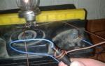
Then we take a block from a laptop and a light bulb, and all these three elements, including the battery, are connected in series with a wire.
Connection diagram.

Connection to the power supply.

The minus of the block is connected to the minus of the battery.


Charging, of course, is a long thing, but it takes a couple of hours to refresh the battery a little.
In general, when my charger burned out, I left such a circuit for the night - and in the morning I received an almost fully charged battery, provided that, of course, it was not discharged to zero.
The current through one 21 watt light bulb is about 1 ampere. If you take two of them, then there will be approximately 2 amperes. In general, it is quite possible to charge a battery in a day, even from scratch.
If you get a chance to measure the battery voltage, then 14.2 is the voltage of a fully charged battery.
Yes, please note that the load current of the unit, look at the case and do not exceed it. Usually it is 3 amps.
Do not forget that when charging, hydrogen is released from the cans of the battery - do not forget about the ventilation of the room.
Use your ingenuity friends, and you can get out of most seemingly hopeless situations.
To recharge the battery, the best option is a ready-made charger (charger). But you can do it yourself. There are many different ways to assemble a homemade memory device: from the simplest circuits using a transformer, to pulse circuits with the ability to adjust. The average in terms of complexity of execution is a memory from a computer power supply. The article describes how to make a charger from a computer power supply for a car battery with your own hands.
[ Hide ]
Manufacturing instructions
Converting a computer PSU into a charger is not difficult, but you need to know the basic requirements for a charger designed to charge car batteries. For a car battery, the charger must have the following characteristics: the maximum voltage supplied to the battery must be 14.4 V, the maximum current depends on the charger itself. It is these conditions that are created in the electrical system of the car when recharging the battery from the generator (video by Rinat Pak).
Tools and materials
Considering the requirements described above, to make a memory device with your own hands, you first need to find a suitable power supply. Suitable used ATX in working order, the power of which is from 200 to 250 watts.
As a basis, we take a computer that has the following characteristics:
- output voltage 12V;
- rated voltage 110/220 V;
- power 230 W;
- the value of the maximum current is not more than 8 A.
Of the tools and materials you will need:
- soldering iron and solder;
- screwdriver;
- 2.7 kΩ resistor;
- 200 Ohm and 2 W resistor;
- 68 ohm and 0.5 W resistor;
- resistor 0.47 ohm and 1 W;
- resistor 1 kOhm and 0.5 W;
- two capacitors for 25 V;
- 12 V automotive relay;
- three diodes 1N4007 for 1 A;
- silicone sealant;
- green LED;
- voltammeter;
- "crocodiles";
- flexible copper wires 1 meter long.
Having prepared all the necessary tools and spare parts, you can begin to manufacture a battery charger from a computer power supply.
Action algorithm
Charging the battery must be carried out under voltage in the range of 13.9-14.4 V. All computers work with a voltage of 12V. Therefore, the main task of the alteration is to raise the voltage coming from the PSU to 14.4 V.
The main alteration will be carried out with the PWM mode of operation. For this, the TL494 chip is used. You can use a PSU with absolute analogues of this circuit. This circuit is used to generate pulses, and also as a power transistor driver, which performs the function of protecting against high currents. To regulate the voltage at the output of the computer power supply, the TL431 chip is used, which is installed on an additional board.

There is also a tuning resistor, which makes it possible to adjust the output voltage in a narrow range.
Work on the alteration of the power supply consists of the following steps:
- For alterations in the block, you first need to remove all unnecessary parts from it and solder the wires. In this case, the 220/110 V switch and the wires going to it are superfluous. The wires should be unsoldered from the PSU. The unit requires a voltage of 220 V to operate. By removing the switch, we will eliminate the possibility of the unit burning if the switch is accidentally switched to the 110 V position.
- Next, solder, bite off unnecessary wires, or use any other method to remove them. First, we look for the blue 12V wire coming from the capacitor, we solder it. There can be two wires, both must be soldered. We only need a bundle of yellow wires with a 12 V output, leaving 4 pieces. We also need a mass - these are black wires, we also leave 4 of them. In addition, you need to leave one green wire. The remaining wires are completely removed or soldered.
- On the board, along the yellow wire, we find two capacitors in a circuit with a voltage of 12V, they usually have a voltage of 16V, they must be replaced with 25V capacitors. Over time, capacitors become unusable, so even if the old parts are still in working condition, it is better to replace them.
- At the next stage, we need to ensure the operation of the unit every time it is connected to the network. The fact is that the power supply unit in the computer works only if the corresponding wires in the output bundle are closed. In addition, overvoltage protection must be excluded. This protection is set in order to disconnect the power supply from the mains if the output voltage supplied to it exceeds a specified limit. It is necessary to exclude protection, since a voltage of 12 V is acceptable for a computer, and we need to get 14.4 V at the output. For built-in protection, this will be considered an overvoltage and it will turn off the unit.
- The shutdown overvoltage action signal as well as the enable and disable signals pass through the same optocoupler. There are only three optocouplers on the board. With their help, communication is carried out between the low-voltage (output) and high-voltage (input) parts of the PSU. In order for the protection not to work in case of overvoltage, it is necessary to close the contacts of the corresponding optocoupler with a solder jumper. Thanks to this, the unit will always be in the on state if it is connected to the mains and will not depend on what voltage the output will be.
- Then, in order to obtain a stable output voltage at idle, it is necessary to increase the load on the PSU output through the channel where the voltage was 12 V, and it will become 14.4 V, and through the 5 V channel, but we do not use it. A 200 ohm, 2 W resistor will be used as a load for the first 12 V channel, and a 68 ohm, 0.5 W resistor will be used to load the 5 V channel. Once these resistors are in place, the no-load output voltage at idle can be adjusted to 14.4V.
- Next, you need to limit the current at the output. For each power supply it is individual. In our case, its value should not exceed 8 A. To achieve this, you need to increase the value of the resistor in the primary winding circuit of the power transformer, which is used as a sensor used to determine the overload. To increase the rating, the installed resistor must be replaced with a more powerful one with a resistance of 0.47 ohms and a power of 1 watt. After this replacement, the resistor will function as an overload sensor, so the output current will not exceed 10 A even if the output wires are shorted, simulating a short circuit.
- At the last stage, you need to add a protection circuit for the power supply from connecting the charger to the battery with the wrong polarity. This is the circuit that will really be created with your own hands and is not in the computer's power supply. To assemble the circuit, you will need a 12 V automotive relay with 4 terminals and 2 diodes rated for a current of 1 A, for example, 1N4007 diodes. In addition, you need to connect the green LED. Thanks to the diode, it will be possible to determine the state of charge. If it glows, it means that the battery is connected correctly and is being charged. In addition to these details, you also need to take a resistor with a resistance of 1 kOhm and a power of 0.5 W. The figure shows the protection circuit.
- The principle of operation of the scheme is as follows. The battery with the correct polarity is connected to the output of the charger, that is, the power supply. The relay is activated by the remaining energy in the battery. After the relay is activated, the battery starts charging from the assembled charger through the closed contact of the PSU relay. Charging will be confirmed by a glowing LED.
- To prevent overvoltage that occurs during the disconnection of the coil due to the electromotive force of self-induction, a 1N4007 diode is connected in parallel with the relay circuit. It is better to glue the relay to the heatsink of the power supply with silicone sealant. Silicone retains its elasticity after drying and is resistant to thermal stresses such as contraction and expansion, heating and cooling. When the sealant dries, the remaining elements are attached to the relay contacts. Instead of sealant, bolts can be used as fasteners.
- It is better to select wires for the charger in different colors, for example, red and black. They should have a cross section of 2.5 square meters. mm, be flexible, copper. The length must be at least a meter. At the ends of the wires, they must be equipped with alligator clips, special clips, with which the charger is connected to the battery terminals. To fix the wires in the case of the assembled device, you need to drill the appropriate holes in the radiator. Through them you need to pass two nylon ties, which will hold the wires.
 Ready charger
 To control the charging current, an ammeter can also be mounted in the charger case. It must be connected in parallel to the power supply circuit. As a result, we have a memory that we can use to charge the car battery and not only.
Conclusion
The advantage of this charger is that the battery will not be recharged when using the device and will not deteriorate, no matter how long it is connected to the charger.
The disadvantage of this charger is the absence of any indicators by which one could judge the degree of charge of the battery.
It is difficult to tell if the battery is charged or not. You can calculate the approximate charging time by using the readings on the ammeter and applying the formula: current strength in Amperes multiplied by time in hours. It was experimentally obtained that it takes 24 hours, that is, a day, to fully charge a conventional battery with a capacity of 55 A / h.
This charger retains the function of overload and short circuit. But if it is not protected from reverse polarity, you can not connect the charger to the battery with the wrong polarity, the device will fail.
A rechargeable battery is a device that wears out and discharges during operation. To charge the battery, a special device is used, which you can buy or make yourself. We will talk about how to build a charger for a car battery from a computer and laptop power supply below.
[ Hide ]
How to charge a battery from a computer power supply?
The cost of quality chargers is high. Therefore, many car owners decide to convert the ATX power supply from a stationary PC into a memory. This procedure is not particularly complicated, but before proceeding with the task and converting the power supply to charging, which can charge the machine battery, you should understand the requirements that apply to the memory. In particular, the maximum voltage level supplied to the battery should be no more than 14.4 volts in order to prevent rapid battery wear.
The user Vetal in his video showed how you can convert the PSU into a charger.
Getting ready for the task
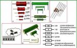
To build a homemade charger from a computer PSU for 200W, 300W or 350W (PWM 3528), you will need the following materials and tools:
- clips ("crocodiles") for connection to the battery;
- resistor element for 2.7 kOhm, as well as for 1 kOhm and 0.5 W;
- soldering iron with tin and rosin;
- two screwdrivers (cross and flat tip);
- resistor elements for 200 ohms and 2 W, as well as for 68 ohms and 0.5 W;
- conventional machine relay for 12V;
- two capacitor elements for 25V;
- three diodes 1N4007 for 1 ampere;
- LED element (any color, but green is better);
- silicone sealant;
- voltammeter;
- two flexible copper wires (1 meter each).
You will also need the power supply itself, which should have the following characteristics:
- output voltage value - 12 volts;
- rated voltage parameter - 110/220 V;
- power value - 230 W;
- the maximum current parameter is not higher than 8 amperes.
Step-by-step instruction
The procedure for charging a machine battery is carried out under voltage, the value of which is from 13.9 to 14.4 volts. All stationary units operate with a voltage of 220 V, so the primary task is to reduce the operating parameter to 14.4 V. The charging device is based on the TL494 (7500) chip, in its absence, you can use an analogue. The microcircuit is needed to generate signals and is used as a driver for a transistor element designed to protect the device from high current. On the additional power supply board there is another circuit - TL431 or another, similar, designed to adjust the output voltage parameter. There is also a resistor element for tuning, with which you can adjust the output voltage in a narrow range.
Learn more about how to convert a computer PSU into a battery charger for a car battery, learn from the video published by the Soldering TV channel.
To make your own conversion of a PSU from a computer into a charger for a car, read the diagram and follow the instructions:
- To begin with, it is necessary to dismantle all unnecessary components and elements from the ATX computer PSU, after which the cables are soldered from it. Use a soldering iron to avoid damaging the contacts. It is necessary to remove the 220/110 volt switch with cables connected to it. By removing the switch, you can prevent the PSU from burning out if you accidentally switch it to 110V.
- Then, unnecessary cables are unsoldered and removed from the device. Remove the blue wire connected to the capacitor element, use a soldering iron. In some PSUs, two wires are connected to the capacitor, both should be removed. Also on the board you will see a bundle of yellow cables with a 12 volt output, there should be four of them, leave them all. There should also be four black wires, they must also be left, since this is ground or ground. It is necessary to leave one more green posting, all the rest are removed.
- Pay attention to the diagram. On the yellow wire, you can find two capacitor elements in a 12 volt electrical circuit. Their operating voltage is 16V, so immediately remove them by soldering and install two 25V capacitors. The capacitor elements swell and become inoperable. Even if they are intact and seemingly working, we recommend changing them.
- Now we need to complete the task so that the power supply is automatically activated every time it is connected to the household network. The bottom line is that when the PSU is installed in a computer, its activation is carried out in the event of the closure of certain contacts at the output. It is necessary to remove the protection against power surges. This element is designed to automatically disconnect the computer's power supply from the household network in case of overvoltage. You need to remove it, because the PC requires 12 volts for optimal operation, and 14.4 V is needed for the charger to function. The protection installed in the unit will perceive 14.4 volts as a power surge, as a result of which the charger will turn off and will not be able to charge the battery car.
- Two pulses pass to the optocoupler on the board - actions from protection against power surges, shutdown, as well as activation and deactivation. In total, there are three optocouplers in the circuit. Thanks to these elements, the connection between the input and output components of the block is carried out. These parts are called high voltage and low voltage. In order for the protection not to work during power surges, you should close the contacts of the optocoupler, this can be done using a jumper made of solder. This action will ensure the uninterrupted operation of the PSU when it is included in the household network.
- Now we need to ensure that the value of the outgoing voltage is 14.4 volts. To complete the task, you will need the TL431 board installed on the additional circuit. Thanks to this component, the voltage is adjusted on all channels coming from the device. To increase the operating parameter, you will need a tuning resistor element located on the same circuit. With it, you can increase the voltage to 13 volts, but this is not enough for optimal operation of the charger. Therefore, a resistor connected in series with the trimmer must be replaced. It should be unsoldered, and a similar part should be installed instead, the resistance of which should be below 2.7 kOhm. This will increase the adjustment range of the output parameter and get the required 14.4 volts.
- Remove the transistor element installed next to the TL431 board. This detail can adversely affect the functionality of the circuit. The transistor will prevent the device from maintaining the desired output voltage. In the photo below you will see the element, it is marked in red.
- In order for the battery charging device to have a stable output voltage, it is necessary to increase the operating load parameter through the channel where the voltage of 12 volts passed. There is an additional channel for 5 volts, but it is not necessary to use it. To provide the load, a resistor component is required, the working resistance value of which will be 200 ohms, and the power will be 2 watts. A 68 ohm part is installed on the additional channel, the power value of which is 0.5 watts. When the resistor elements are soldered, you can adjust the output voltage to 14.4 volts without the need for a load.
- Then the output current should be limited. This parameter is individual for any power supply. Our current strength should be no more than 8 amperes. To ensure this, it will be necessary to increase the value of the resistor component installed in the primary circuit of the winding, next to the transformer device. The latter is used as a sensor designed to determine the overload value. To increase the nominal value, the resistor must be replaced, a component with a resistance of 0.47 Ohm is mounted instead, and the power value will be 1 W. The resistor is carefully soldered, a new one is soldered in its place. After completing this task, the part will be used as a sensor, so the output current will be no more than 10 amps, even if a short circuit occurs.
- To protect the machine battery from reverse polarity, when connecting a home-made charger, an additional circuit is installed in the device. This is a board that you have to make yourself, since it is not in the block itself. To develop it, you will need a prepared 12 volt relay, which should have four terminals. You will also need diode components, the current strength of which will be 1 ampere. Alternatively, parts 1N4007 can be used. The circuit should be supplemented with an LED that will indicate the state of the charging process. If the light is on, the car battery is connected to the charger correctly. In addition to these components, you will need a resistor element, the operating resistance of which will be 1 kOhm, and the power will be 0.5 W. The principle of operation of the scheme is as follows. The battery is connected via cables to the output of a homemade charger. The relay is activated due to the energy that remains from the battery. After the element is triggered, the charging process from the charger begins, as evidenced by the activation of the diode light bulb.
- When the coil is deactivated, a voltage jump occurs as a result of the influence of the electromotive force of self-induction. To prevent its negative impact on the operation of the charger, two diode components must be added to the board in parallel. The relay is fixed on the PSU radiator device with a sealant. Thanks to this material, elasticity can be ensured, as well as the immunity of parts to thermal stress. We are talking about contraction and expansion, heating and cooling. When the glue dries, the remaining components must be connected to the relay contacts. If there is no sealant, ordinary bolts are suitable for fixing.
- At the last stage, wires with "crocodiles" are connected to the block. It is better to use cables of different colors, for example, black and red or red and blue. This will prevent the polarity from being reversed. The length of the wire will be at least one meter, and their cross section should be 2.5 mm2. Clamps are connected to the ends of the cables, designed to be fixed on the battery terminals. To fix the wires on the body of a homemade charger, two holes of the corresponding diameter are drilled in the radiator device. Two nylon ties are threaded through the resulting holes, with which the cables will be fixed. An ammeter can be mounted in the charger, it will allow you to control the amount of current. The device is connected in parallel to the power supply circuit.
- It remains to test the performance of the self-assembled memory.
1. Red marked jumper on the diagram 2. Transistor element on the board to be removed 3. Resistor element in the primary circuit to be replaced 4. Scheme for assembling a board designed to protect the PSU in case of polarity reversal
Charger from laptop power supply
You can build a charger from a laptop power supply.
You cannot directly connect the PSU to the battery terminals.
The output voltage varies around 19 volts, and the current strength is about 6 amperes. These parameters are sufficient to ensure that the battery is charged, but the voltage is too high. There are two ways to solve the problem.
No PSU modification
It will be necessary to connect the so-called ballast in the form of a powerful lamp from optics in a consistent manner with the car battery. The light source will be used as a current limiter. A simple and affordable option. One contact of the lamp is connected to the positive output of the laptop power supply, and its second contact is connected to the positive of the battery. The minus from the power supply is connected directly to the negative terminal of the battery via a wire. After that, the PSU can be connected to the household network. The method is very simple, but there is a possibility of failure of the light source. This will result in the inoperability of both the battery and the unit.
With alteration of the power supply
You will need to lower the PSU voltage parameter so that the output voltage is about 14-14.5 V.
Consider the process of manufacturing and assembling a charger using the example of a power supply from a Great Wall laptop:
- First you need to disassemble the power supply housing. When disassembling, do not damage it, as it will be used for further operation. The board, which is located inside, can be connected to a voltmeter to find out exactly what its operating voltage is. In our case, it is 19.2 volts. A board built on TEA1751 + TEA1761 chips is used.
- The task of reducing the voltage value is being performed. To do this, you need to find a resistor element located at the output. You need a part that connects the sixth pin of the TEA1761 circuit to the positive terminal of the power supply. This resistor element should be unsoldered with a soldering iron and its resistance measured. The operating parameter is 18 kOhm.
- Instead of the dismantled element, a tuning resistor component of 22 kOhm is installed, but before soldering it should be set to 18 kOhm. Solder the part carefully so as not to damage other circuit elements.
- Gradually lowering the resistance value, it is necessary to ensure that the output voltage parameter is 14-14.5 volts.
- When you get the voltage that is optimal for charging a car battery, the soldered resistor can be soldered off. Its resistance parameter is measured, in our case it is 12.37 kOhm. According to this value or close to it, a constant resistor is selected. We use two resistors of 10 kΩ and 2.6 kΩ. The ends of both parts are installed in thermocambric, after which they are soldered into the board.
- We recommend testing the resulting circuit before assembling the device. The output voltage parameter will be 14.25 volts, which is enough to charge the battery.
- Let's start assembling the device. Connect wires with clamps. Before soldering them, make sure that the output polarity is observed. Depending on the laptop unit, the negative contact can be made in the form of a central wire, and the positive contact can be made in the form of a braid.
- As a result, you get a device that can properly charge the battery. The amount of current during the charge varies in the region of 2-3 amperes. If this parameter drops to 0.2-0.5 amperes, then the recharging procedure can be considered completed. For more convenient use, the charger is equipped with an ammeter, fixing it on the case. You can use an LED lamp that will tell the car owner about the completion of the charging process.
The kt819a channel provided a video that details a charger made from a laptop power supply.
How to properly charge the battery with a homemade charger?
In order to prevent a quick failure of the battery, it is necessary to take into account certain nuances for proper recharging.
- First disconnect the battery terminals from the clamps. Loosen the bolts that secure the battery retainer bar.
- Dismantle the device from the seat, take it home or to the garage.
- Clean the body of dirt. Pay attention to the terminals themselves. If they have oxidation, they should be cleaned. Use a toothbrush or a construction brush, fine-grit sandpaper will do. The main thing is not to clean off the working plaque.
- If the battery is serviceable, open all of its cans and check the electrolyte level in them. The working solution should cover all sections. If this is not the case, then charging the battery may cause the boiling liquid to evaporate rapidly, which will affect the functionality of the battery and its health as a whole. If necessary, add distilled water to the jars. Visually inspect the battery case for defects, sometimes fluid leakage is associated with cracks. If the damage is severe, the battery must be replaced.
- Connect the clamps of the self-made charger to the battery terminals, observing the polarity. After that, the device can be connected to the household network. It is not necessary to unscrew the corks on the banks.
- When the charging procedure is completed, check the electrolyte level and if everything is fine, then tighten the banks. Install the battery in the car and make sure it is in working order.
Conclusion
The main advantage of the device is that the car battery cannot be recharged in the process of recharging. If you forget to disconnect the battery from the charger, this will not affect its service life and will not lead to rapid wear. If you do not equip the charger with an LED indicator, you will not be able to understand whether the battery is charged or not. Alternatively, you can roughly calculate the recharging time using the readings given by the ammeter connected to the charger. You can calculate by the formula: the value of the current strength is multiplied by the charging time in hours. In practice, it takes about a day to complete the task of recharging, provided that the battery capacity is 55 Ah. If you want to visually see the level of recharging, then you can add arrow or digital indicators to the device.