We make an on-board computer. On-board computer and many other do-it-yourself Arduino projects useful for cars
On-board computer for a car- , printed circuit board and microcontroller program available. The rain sensor is assembled on a single-sided printed circuit board made of foil fiberglass, shown in fig. 5. As seen in the photograph of fig. 6, the terminals of the tuning resistors R28 and R29 are bent at an angle of 90 ° so that the resistors themselves are installed with wide edges parallel to the surface of the board and mainly not in its contour. Since the X7 six-pin connector could not fit between the tuning resistors, it is divided into two parts: a four-pin connector installed on the board (pins 3-6) and a two-pin wire suspended on the connecting wires (pins 1 and 2 connected to the R30R31 heating circuit).


The emitting diode and the photodiode of each pair are inclined towards each other so that their longitudinal axes - the directions of maximum radiation and sensitivity - intersect exactly on the outer surface of the windshield, forming a right angle. To achieve this, the slope of the diodes is selected when installing the sensor on the glass, or the thickness of the adhesive gasket between the body and the glass is changed.
rice 7 (1,2)
pic 8 (1.2)
A drawing of the main double-sided printed circuit board of the BC made of foil-coated fiberglass with a thickness of 1.5 mm is shown in fig. 7, and the arrangement of parts on it is shown in Fig. 8. This board is designed to install fixed resistors and capacitors in the main frame size 0805 for surface mounting. Resistors R3 and R36 are conventional MLT, C2-33 or similar imported ones. Trimmer resistors - PV36W or other multi-turn. Capacitors C1 and C12 - size 3216. Relay K1 - K5 G5CLE-14-DC12, they can be replaced by others with 12 V windings, such as automotive ones.
In the ones shown in Fig. 8 filled vias, it is necessary to insert and solder short lengths of bare wire on both sides. Only then can you start soldering the surface mount components, and then the rest of the parts, connectors and three jumper wires. For the G1 lithium cell, it is necessary to install a holder on the board, which can be found on the motherboard of an old computer, and a sound emitter (HA1) can also be found there.
At the end of the installation, the engines of all tuning resistors are set to the middle position and the program is loaded into the microcontroller. Any in-circuit programmer capable of working with ATmega64 microcontrollers is suitable for this. Separately, I want to recommend the one that is described in the article by S. Sokol “A miniature USB programmer for AVR microcontrollers” (“Radio”, 2012, No. 2, pp. 27-30). The programmer is connected to connector X10. The microcontroller configuration is set in accordance with Fig. 9 in the window of the program serving the programmer.
By applying voltage +12 V to pin 2 of connector X1 BC, the programming procedure is performed. If it was successful, you can connect the HG1 LCD to the X3 connector, and the SB2-SB5 buttons to the X5 connector and start setting up the BC. Now, immediately after the power is turned on, the LCD screen should display an image similar to that shown in Fig. 10.

By connecting a DC voltmeter between pins 2 (+) and 1 (-) of connector X1, using the trimmer resistor R7, we achieve equality of the readings of this voltmeter and the one displayed on the LCD BC. Then set the trimming resistor R20 to the desired brightness of the backlight of the LCD screen. If you plan to use a pointer speedometer, you must activate it in the "Other" menu, and then go to the speedometer calibration menu.
Immediately after turning on the switches to operating mode. If you now press the SB3 "Select" button, the place of the inscription "STOP", meaning that the engine is not running, will be taken by the clock. Repeated presses on the same button will display the readings of the daily odometer, then a constant (non-resettable) odometer and again the tachometer (“STOP” with the engine stopped) on the LCD.

Pressing the SB2 "Menu" button will display the main menu of the BC on the LCD (Fig. 11). Pressing it again will move the cursor (selection of text by inversion) one position down, and upon reaching the end of the menu - to its beginning. Having highlighted the desired item, press the SB3 "Select" button. When the “Exit” item is highlighted, pressing this button returns the BC to the main operating mode.
Consider the menu items "SETUP" in order:
"Mode". In this item, it is possible to select one of the four available modes of displaying information on the LCD provided in the microcontroller program. To go to its selection, you should, having highlighted this item, press the SB2 button again. The image will change to the one shown in fig. 12.


Near the current mode, the inscription "ok" is displayed, to select another mode, select the desired line and press the SB3 button. The "ok" label will move to the selected item. To return to the main menu, highlight the line "Exit" and press the SB3 button or, regardless of the cursor position, press the SB4 button.
"Mode 1" corresponds to the image in fig. 10. When “Mode 2” is selected, the location of the speedometer and tachometer readings will change places with a corresponding change in the size of the numbers, and the icons will be moved to another place on the screen (Fig. 13).


This mode is convenient for vehicles that do not have a tachometer on the instrument panel. In "Mode 3" (Fig. 14) there are no speedometer and tachometer readings on the LCD. Instead, the results of the operation of odometers are displayed: daily (resettable), and below it - constant (not resettable). The SB3 button does not work in this mode. This mode is suitable for those who are satisfied with the work of the factory speedometer and tachometer installed in the car. "Mode 4" has not yet been implemented. When selected, a message will be displayed and "Mode 1" will be set.
On-board computer diagram shown in fig. 2. Its basis is the ATmega64-16AUR (DD1) microcontroller, operating at a clock frequency of 16 MHz, set by the ZQ1 quartz resonator. A programmer is connected to the X10 connector for programming the microcontroller already installed on the BC board.
Through the three-pin connector X1, the on-board computer is powered from the vehicle's on-board network, with the body of which the contact 1 of the connector is connected. Pin 2 is connected directly to the positive battery terminal. Pin 3 is supplied with +12 V after the ignition switch. It is marked on the U ACC diagram and should only appear when the ignition key is turned to the appropriate position.
From pin 2 of connector X1 the voltage of the on-board network is supplied to the integral stabilizer LM317S (DA1), the resistors R1 and R2 are selected so as to obtain 5 V at the output of the stabilizer to power all the nodes of the on-board computer, except for the LCD HG1. The voltage of 3V for the indicator was obtained using the integral stabilizer 78L03 (DA2).
The voltage U ACC through the limiter of the resistor R10 and the zener diode VD2 is fed to the input PD3 of the microcontroller DD1. If the clipped high on this input is not present for more than a minute, the microcontroller enters a low power sleep mode. The work of the bookmaker (with the exception of the time count) is suspended. With the appearance of this level, when turning the ignition key to the appropriate position, the microcontroller will “wake up” and the BC will work.
The U ACC voltage is also used to power the path sensor connected to the X4 connector. Any that generates from 600 to 27,000 pulses per kilometer is suitable. During the calibration of the odometer and speedometer, this number will be taken into account automatically. You can use the factory-installed sensor in the car's gearbox. Its common (negative) wire is connected to pin 1 of the X4 connector, to pin 2 - a wire on which pulses are generated during movement, the number of which is proportional to the distance traveled, and to pin 3 - the positive wire of the sensor power supply. 
If the car is equipped with ABS, you can use the sensor available in this system. Its output is connected to pin 2 of connector X4 with a shielded wire (braided to pin 1 of the connector). Unfortunately, in practice, the operation of the on-board computer circuit with such a sensor has not been verified, although according to the calculations, everything should function correctly.
Finally, one can apply
a home-made path sensor, for example, consisting of four to eight permanent magnets fixed around the circumference on one of the axle shafts of the car, and a Hall sensor that responds to their alternate approach during the rotation of the axle shaft.
Regardless of the type of sensor, its pulses are fed to an amplifier assembled on a VT5 transistor, and amplified pulses are sent to the PD0 input of the DD1 microcontroller.
"Odometer". Its calibration is very similar to speedometer calibration. Having reset the odometer readings by pressing the SB1 button, it is necessary to drive along a straight route of known length, for example, measured using a satellite navigator. Then, having selected the “Odometer” item in the “Calibration” menu, we get an image on the LCD similar to that shown in Fig. 19. Here 6980 m is the length of the route measured by the BC, 326 is the calibration number, which should be in the range 5-9999. Knowing the exact length of the route, we make a proportion similar to that used in the calibration of the speedometer, taking into account that an increase in the calibration number in this case reduces the odometer readings of the BC, and vice versa. Having solved the proportion, we find a new value of the calibration number and enter it using the items "+10", "-10", "+1", "-1". The result of the calibration is entered into the memory of the BC using the "Save" item.
"Dat. Sveta".
To properly adjust the light sensors, you should wait until the evening so that it is such that you already need to turn on the side lights, but it's too early to turn on the headlights. When you select "Date. light” the image on the LCD will take the form shown in Fig. twenty.
The line "Ex. light YES" means that the control of lighting devices by the signals of the light sensor will begin to operate immediately after the ignition is turned on. When the word “NO” is set in this line, such control is normally turned off, but it can be turned on and off by pressing the SB4 “Light” button or control the lighting using the factory switches.
Parameters "d1" and "d2" - current levels of sensor signals (photodiodes VD22 and VD23). Please note that the indicator displays the hexadecimal values of these parameters, as well as the thresholds for turning on the parking lights and headlights. To set the thresholds, go by pressing the SB2 button to the line “On. size" and then "On. headlights "and using the SB3 button set the desired values. Usually, the threshold for turning on the headlights is set 3-7 units less than the threshold for turning on the parking lights.
Two sensors illumination is used to reduce the likelihood of false positives. Lighting devices will turn on only when the signal levels of both sensors are below the threshold. If it is necessary, according to the requirements of the traffic rules, to turn on the headlights or daytime running lights with the start of movement, regardless of the external illumination, this is done using the “Turning on additional headlights” function discussed below. In this case, the thresholds for turning on headlights and side lights according to the signals of light sensors must be set deliberately high, for example, 35 units.
"Dat. rain." The LCD image corresponding to this item is shown in Fig. 21. Note that here again all numbers are hexadecimal. The top line allows you to turn the rain sensor on and off. The second and third lines display the values of the photodiode signal levels measured with the emitting diodes switched off (off) and switched on (on). The fourth line displays the values of the difference between off and on levels for the first (VD8, VD10) and second (VD9, VD11) pairs of diodes. The next line specifies the threshold value of the difference (in this case 19), above which the wiper will be turned on.
Sensor adjustment must be carried out directly on the vehicle. It is recommended to do this in the evening or on cloudy days to minimize the effect of sunlight. First of all, trimming resistors R46 and R47 set the "off" values in the range of 1-4 and equal for both pairs. Then trimming resistors R28 and R29 are set equal to "on". If, when the position of the variable resistor slider changes, the “on” value does not change, it is necessary to slightly, literally by a fraction of a degree, change the angle of mutual inclination of the diodes of the corresponding pair. The difference between "off" and "on" values must be at least 15 units.
Having achieved this, we apply on the outer surface of the windshield with a syringe in sensitive areas a pair of diodes by a drop of water. The difference values should decrease by 5-7 units, but after wiping the glass, return to the original ones. The response threshold is recommended to be set equal to or slightly less than the arithmetic mean of the difference obtained for two pairs in the presence of water drops on the glass.
If in the daytime the “off” values \u200b\u200bare reached FF and they cannot be reduced by tuning resistors R46 and R47, a light-absorbing film is laid between the windshield and the sensor, for example, used for tinting car windows. The sensor adjustment is repeated again.
For several months of operation, not a single false alarm of the rain sensor was observed, the program monitors and corrects its operation, if possible, and if not, the sensor turns off for a while.
"Ust. ode."
This item refers to a permanent (non-resettable) odometer that calculates the total mileage of the car. It is available only for the first twenty inclusions of the BC. Here you can set the initial value of the odometer reading so that it continues the calculation of the mileage started by the device previously present on the car. The LCD screen takes the form shown in fig. 22. By pressing the SB2 button, the selection is moved from digit to digit, and using the SB3 button, the selected digit is changed in the range 0-9. This makes it possible to set any initial value, up to 999999 km. When the mileage is dialed, go to the “Save” item, press the SB3 (Select) button, and if everything is typed correctly, the message “Value saved” will appear on the screen. The item remains available for changes until the BC counts 20 inclusions.
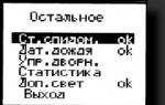
« Rest«.
This is the last item on the main menu. When it is selected, the LCD displays the submenu shown in Fig. 23.
In line « Art. AIDS.«
the dial speedometer can be turned on or off. To use such a speedometer, it must first be calibrated by selecting the “Speedometer” item of the “Calibration” menu with the arrow speedometer activated. At the same time, in the image on the LCD, in contrast to the previously considered one (see Fig. 18), a new line “Arrow = 80” will appear (Fig. 24), and the speedometer needle will smoothly deviate to a position corresponding to a speed of 80 km/h.
Using a tuned resistor R21, it must be set exactly to the corresponding scale division. Next, highlight the line "Arrow = 80" and press the SB3 button. The speed value will gradually increase to 120 km/h and gradually decrease to zero. The speedometer needle will follow him. Then the cycle will repeat. This will allow you to check the correctness and accuracy of the speedometer.
In line " Date rain
» enable and disable the control of the wiper from the rain sensor, and in the line «Control. janitor." - wiper control using the SB5 button. You can choose the first or second control method, or even prohibit the BC from controlling the wiper.
When you select the "Statistics" line, the LCD displays information about the engine operation time and travel time in hours and minutes (Fig. 25). You can reset it in two ways: by selecting the appropriate menu item or by long (more than 3 s) pressing the SB1 button. In the latter case, both the statistics and the odometer will be reset to zero.
Line " Add. light«
allows you to turn the daytime running light control on or off. If it says “ok”, this function is active. The lights will turn on immediately after the start of the movement, regardless of weather conditions and time of day, and turn off when the engine is stopped.
All set parameters, odometer results and statistics are stored in the non-volatile memory of the microcontroller and are saved when the power is turned off.
According to the algorithm embedded in the microcontroller program, immediately after turning the ignition key, the BC starts working, displaying information on the LCD according to the selected mode. If the oil change warning function is enabled and less than 2000 km is left to drive, a corresponding message will be displayed, and after 2 s the BC will return to working mode. After starting the engine, the tachometer will display the speed of the crankshaft, and as soon as the car starts moving, the speedometer will show its current speed.
When dusk comes and BC
will automatically turn on the parking lights, their icon will appear on the LCD. When it gets completely dark and the low beam headlights turn on, the icon will take the form of a headlight on.
If the ignition is turned on at night, the parking lights will turn on immediately, and the low beam will turn on when the car starts to move. At dawn, the headlights will be turned off first, and then the parking lights. These lights, and if necessary, headlights, will also turn on when entering a dark tunnel. If at night the car remains stationary for more than 5 minutes, the headlights will be turned off, and the parking lights will remain on. The headlights will turn on as soon as the vehicle starts moving. You can forcibly turn off the parking lights and headlights by pressing the SB4 button. Pressing it again will return the BC lighting control. Since the factory-installed light switch remains in place, you can use it.
Where the rules of the road
require you to turn on the lights while driving, regardless of the time of day, you can use the corresponding function. When it is active, starting the vehicle while the engine is running will turn on the daytime running lights. They will turn off as soon as the engine is turned off.
If the windshield wiper is controlled by the rain sensor, it will work as soon as raindrops appear on the windshield in the sensor's coverage area. The windshield wiper speed is automatically selected depending on the intensity of the rain and the speed of the vehicle. You can forcibly turn off the wiper by pressing the SB5 button, and pressing it again will turn on the control by sensor signals. You can turn on the wiper and windshield washer manually using the standard switch.
If in the SETUP menu the wiper control is set with the SB5 button, then the first press of it will turn on the wiper operation with pauses, the duration of which depends on the speed of the vehicle. Pressing again will turn on continuous operation of the wiper at a low speed, the third will turn on the high speed, and the fourth will turn it off. You can stop the wiper, regardless of the selected mode, by long (more than 5 s) pressing the SB5 button. All operating modes of the wiper are displayed as pictograms on the LCD.
If the voltage of the on-board network the battery icon and a description of the problem will appear on the LCD, a beep will sound three times, and the LCD backlight will flash the same number of times. The BC will then return to normal operation. When the temperature outside the car is close to zero, the LCD shows the “Slippery road” icon and the inscription “Attention! Ice is possible." These warnings cannot be blocked.
BC constantly monitors the condition of the doors, hood and trunk. As soon as at least one door, hood or trunk is opened, a picture will appear on the LCD showing their status (Fig. 26). The return to operating mode will occur when everything is closed, or after pressing the SB3 button.
After turning the ignition key in the “OFF” position of the headlights, the parking lights and the wiper (if they were on) will turn off instantly, and the BC itself - in about a minute. If a door, hood or trunk remains open after turning the key, the BC will not turn off, displaying their status until everything is closed.
Archive for the article ….Download
I. MAZURENKO, Odessa, Ukraine
"Radio" №1 2013
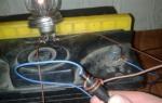
The display of a self-made on-board computer is a transparent illuminated image of a car, on which 9 holes are drilled, in which miniature red light bulbs (LEDs) are installed. The acoustic signaling device is located in any convenient place behind the display. If the car is on the handbrake and the ignition is turned on, the NC light will come on and a double warning signal will sound, repeating every few seconds while the ignition is on. Indicator of depressurization of the brake system. When this fault occurs, it is lit and an intermittent audible signal sounds continuously. H1 lights up when the pressure in the lubrication system of the car engine drops with the ignition on. At the same time, a four-time acoustic signal is heard, repeating every 2 minutes.
In addition to the brake sensors "T.Ts." (central brake) and "R.T." (handbrake) also uses an insufficient oil pressure sensor (terminal "M") without alteration. Door sensors "D1-D4", hood "K" and trunk "B" are installed additionally. These are the same microswitches as the regular interior lighting switches located in the doorways. When the door is closed and the switch button is pressed by it, there is no contact. When the door is opened, the button is released and closes the conductor to ground. Such sensors are additionally installed in the openings of all four doors, as well as at the hood lock and on the opening of the trunk lid (fifth door).
A diagram of a self-made on-board computer, taken from the radio designer 2002 magazine, is shown in the figure below.

Clock pulses with a frequency of 32 Hz are fed to the input of the binary counter D2 from the multivibrator on the elements D1.2 and D1.2. Zeroing of the counter is controlled by "NAND" D5.1. At the moment of power-up, the charging current C2 through R2 sets the counter to zero. The power is turned on simultaneously with the ignition. While the ignition is on, the counter constantly runs in a circle.

There are three RS flip-flops on the D3 chip. The first trigger is set to zero at the moment the ignition is turned on. Its output will be zero, which is present there until the counter D2 counts from zero to three half-second pulses available at its output "8". If one door or several doors, hood, trunk is not closed before turning on the ignition, then a low logic level occurs at the connection point of the diodes VD10-VD15 and R8. Both inputs "2OR-NOT" D4.1 receive zeros, and the output of D4.1 will be one. This leads to zero at the output "4OR-NOT" D6.1 and the element D6.2 starts to pass pulses from the output "8" D2 with a frequency of 2 Hz to the start input of the multivibrator D5.2-D5.3, which generates pulses with a frequency of 1 kHz, which, through VT1, are fed to the emitter B1.

Therefore, if the car was not completely closed before turning on the ignition, then, in addition to the light indication on the display, three warning sound tones are heard. The second trigger D3 works with the handbrake. If it is up, the P.T. closes to ground. Charging current C4 sets counter D2 and trigger T2 to zero. At the output of trigger T2, zero occurs, and, just as in the case of an open door, the buzzer turns on. After two sound pulses, a logical unit appears at the output "32" of counter D2. And this returns the T2 trigger to a single state. The buzzer turns off. However, if the closed action of the handbrake sensor is not terminated, after four seconds, a unit appears at the output "128" D3, which, using the circuit C9-R14, creates a positive pulse that resets trigger T2. And the double beep is repeated again. And so, every four seconds, until the handbrake lever is lowered.

The device also works when the low oil pressure sensor is triggered. But here another TK trigger is involved, the sound signal is four times, and the repetition is every 2 minutes. In case of violation of the tightness of the brake system or leakage of brake fluid, the VD4 cathode closes to ground. At the output of D1.4, a unit appears and an intermittent sound signal sounds constantly.

The display screen is made of a sheet of Plexiglas, which is evenly colored in dark blue, and on it, according to the paint, an image of a car is engraved. If you illuminate the display with a green lamp (H10) from the inside, a green image of the vehicle lights up against a dark background. Holes were drilled in the right places of the display, into which automobile baseless signal lamps H1-H9 (or LEDs), painted in red, are tightly inserted. The tone of the acoustic signal is set by selecting the resistor R4, and the duration of the sound - R1. This on-board computer has been working without interruption for several years.
Forum on homemade on-board computers
Discuss the article ON-BOARD COMPUTER OWN HANDS
The on-board car computer or the "brains" of the car is the most important element for controlling and monitoring the performance of all the main components of the vehicle. BC is put today on all modern cars. You can learn more about the principle of operation and varieties from this material.
[ Hide ]
Description of the on-board computer
What is an on-board computer in a car and what tasks does it perform? First, let's look at some theoretical points. BC is an electronic unit that allows you to respond and control various processes in the operation of various auto systems. That is, thanks to the BC, the driver will always be able to receive data on the operation of certain components. We figured out what an on-board computer is, now we’ll talk about its purpose.
What the on-board computer shows:
- the device demonstrates the consumption of gasoline in different driving modes;
- allows you to control the nozzles, as well as the ignition system of the vehicle;
- controls the operation of the transmission;
- can control various additional two-way communication systems, for example, a rear-view camera, etc.;
- allows you to determine the level of pressure of the motor fluid, the temperature of the antifreeze;
- regulates the voltage level in the electrical circuit of the car, controls the battery charge;
- if the vehicle is equipped with a climate control system, then the BC controls it;
- one of the main options - the on-board computer for a car allows, if necessary, to read error codes and show them on the display so that the driver can decipher them and find out where to look for a breakdown.
Principle of operation
The principle of operation of an automobile BC for carburetor engines or injection options is not particularly complicated. The device connects to a chain of controllers and regulators, reads the necessary data, and then processes the information received. Special software is used for processing. For example, if the BC receives data on fuel consumption according to the scheme, then the software will allow you to calculate the possible mileage on the remaining amount of gasoline.
All data is displayed on a screen installed in the vehicle interior. The display itself can be digital, monochrome, color, or four or three digits. As practice shows, a 2-inch monochrome screen is enough to show the driver more than ten parameters. More modern versions of the BC today are equipped with a high-precision liquid crystal display.
Kinds
To date, there are several types of BC:
- universal option, such a device combines various options and gives the car owner the opportunity not only to drive the car, but also to surf the Internet. The main purpose of such a device is to increase the comfort for the car owner while driving. Typically, a universal on-board computer has a screen with a diagonal of 6-14 inches; a keyboard can be connected to newer models. It should be noted that in their design such BCs are very similar to ordinary computer PCs, but one of the features of the devices is a low degree of integration with the car's electrical system.
- Route. The trip on-board computer allows you to determine the driving parameters of the car, while it is not necessary to connect it via GPS to the satellite. However, newer models are equipped with GPS receivers anyway. With the help of such a device, the driver will be able to determine the average speed of the car, fuel consumption, the remaining distance to a particular point, the distance traveled, etc. In addition, depending on the model that you install in your car, the device may have the function of calculating fuel consumption during emergency braking or rapid acceleration. Typically, BC of this type are installed in the control panel.
- Manager and service BC. The purpose of such computers is to determine the breakdowns of the main units of the vehicle and warn the car owner about this. As a rule, such a BC is an integral part of the machine control system, but depending on the model, it can also be an independent device with extensive functionality. When checking a car, all combinations of errors are stored in the device’s memory and will remain there until the error is corrected and the memory is reset (the author of the video is the AvtoGSM channel).
Bookmaker setup
Making an on-board computer with your own hands is a difficult task at home. To make a device, you will need many different elements, including a display, a microcircuit, buttons, etc. It is impossible to make a computer on your own without the experience of assembling such devices, so if you want the device to work correctly, then it is better to order this procedure or buy a new BC.
If you decide to install an on-board computer for carburetor or injection engines on your car, then you need to know how the device is configured correctly:
- If necessary, you can always activate the automatic configuration option - then the device itself will take the necessary configuration.
- If this option does not suit you, then go to the settings menu - find the desired block and select it. It should be noted that in this case, the BC must be configured as the main device. One of the important roles in the setting is determined by the choice of mode, due to which the fixing of fuel costs will be carried out.
- By setting this parameter, you have several options. One of them is a linear relationship, in which case the parameter will always depend on the control unit. If you decide to manually adjust, then first you will need to make a table on fuel consumption. Given this information, the bookmaker will carry out calculations and display the relevant parameters on the screen.
- In addition, you will need to determine the parameters that the screen will start to show, depending on the model, their number may be different. Separately, it is necessary to highlight the parameter responsible for the activation temperature of the motor cooling fan.
Issue price
The minimum cost of a bookmaker from Multitroniks will be around 130 rubles. More expensive options may cost 7,500 rubles.
Sorry, there are currently no surveys available.
Video "How to make a BC with your own hands"
Detailed instructions for making the circuit are presented in the video (the author is the libral1973 channel).
Technology does not stand still and today motorists are offered many different options for improving their "iron horses". One of these is the Arduino. This device is a tool used to design electronic devices. In the case of a car, the design is usually done on the windshield. How to make an on-board computer on Arduino and how to set it up correctly - read this article.
[ Hide ]
Ideas for cars based on a small board with a small processor - Arduino
Computers have long and densely entered our lives. The Arduino hardware platform is one of the latest open source developments that is built on a conventional printed circuit. We will tell you more about how to make different devices for cars using such a board.
BC
Using the Arduino board, you can build a car on-board computer that can:
- calculate fuel consumption;
- display information about the temperature of antifreeze;
- calculate the speed of movement, as well as the distance of the trip;
- withdraw the spent fuel for a certain mileage;
- determine the speed of the motor, etc. (the author of the video is the Arduino Tech PTZ channel).
In addition to the Arduino device, you will also need a liquid crystal module, an HC-05 Bluetooth adapter, as well as an ELM327 scanner and a 10 kΩ resistor device. Of course, it is also necessary to prepare a sound indicator, mounting wires and the device case itself.
The assembly procedure is as follows:
- First, set up the Bluetooth adapter. You need to solder the wires to the pins of the device - to the two lower and upper contacts.
- The module itself is connected to the board for configuration, for this you need to open the Arduino IDE 1.0.6 program or any other version, after which you upload the sketch to the circuit via the USB output.
- When the download is complete, you need to go to the menu Tools - Port Monitor and set the speed to 9600.
- Then a circuit is assembled with a board, an adapter and a pre-prepared display. The Bluetooth adapter is connected first.
- After that, a display is added to the circuit. A more detailed description of the connection can be found in the photo below.
- A 10 kΩ resistor element is used to control the brightness and contrast of the display. Therefore, when you first connect, you may notice that there is no image, if so, then you just need to adjust it by turning the resistor.
- Next, an additional key is connected, which will perform the function of switching screens with information. One contact from the button goes to the GND element, the second - to pin 10. To connect the beeper, the positive contact is connected to pin 13, and the negative contact is connected to GND.
- Then, using the same Arduino IDE 1.0.6 software, upload the sketch. Now you just have to set up the on-board computer and connect it to the car.
Photo gallery "BK connection diagram"
GPS tracker
To assemble an Arduino-based GPS tracker, you will need:
- the board itself, the process is described using the example of the Mega 2560 model;
- GSM/GPRS module that will be used to transfer data to the server;
- as well as an Arduino GPS receiver, in the example we will consider the SKM53 model (the author of the video on making a tracker using the SIM 808 board as an example is the Alex Vas channel).
How the circuit is connected:
- First, the module is connected to the main board, the default baud rate is 115200.
- After connecting, you need to turn on the device and set the same speed for all ports - both serial and software.
- The GSM transmitter is connected to pins 7 and 8 on the main chip.
- Then the module is configured by entering commands. We will not describe all the commands, they can be found on the Internet without any problems. Let's consider only the most basic ones. AT+SAPBR=3,1,"CONTYPE","GPRS" - the command determines the type of connection, in this case it is GPRS. AT+SAPBR=3,1,"APN","internet.***.ru", where *** is the address of the mobile network operator to be used. AT+HTTPINIT - this command initializes HTTP.
- One nuance should be noted - when writing the server component of the interface, it is desirable to provide for the reception and output of data for several adapters. You need to set the switch to three positions, this will make it possible to receive data from eight cars.
- Then the sketch is written on the chip. The sketch itself can also be found on the Web, it is not necessary to write it. Please note that if two active serial ports are used, this may result in errors in transmitting and sending information.
Parktronic
To build a parktronic, you will need the following components:
- the microcircuit itself;
- ultrasonic device, in this case it is a range finder HC-SR04:
- six LED elements;
- six resistor elements with a resistance of 220 ohms;
- male-male connecting wires;
- piezodynamic element;
- layout for assembly.
The assembly procedure is as follows:
- To begin with, it is necessary to install LED elements prepared in advance on the breadboard diagram. The negative contact for all LEDs will be common. The short pin, the cathode, should be connected to the negative rail provided on the breadboard.
- The longer diode contacts, i.e. the anodes, need to be connected with 200 ohm resistor elements, if you do not use them, this will burn out the diodes.
- An ultrasonic device is mounted on the central part. There are four pins on this controller. Vcc is the five volt power pin, Echo is the output pin, Trig is the input, and GND is ground.
- After the rangefinder is installed, wiring should be connected to its outputs. In particular, the Echo pin is connected to output 13, Trig - to pin 12. GND, respectively, must be connected to ground, which is available on the controller circuit, and the remaining Vcc output is connected to the 5-volt supply on the Arduino board.
- After completing these steps, you need to connect the wiring to the contacts of the resistor elements. And they are also connected in series to the pins on the board - pins from 2 to 7 are used.
- The next step will be to connect a piezo tweeter, which will warn the driver about approaching an obstacle. The negative output, as an option, can be combined with the negative contact of the previously installed rangefinder. As for the positive contact, it connects to pin number 11 on the chip.
- In order for the device to eventually work in normal mode, you will additionally need to write, and then download the program code to the board. In this code, you must accurately specify the distance, when approaching which the diode elements will start to light up and the buzzer will work. Moreover, the tone of the tweeter should be different so that the driver can find out when the approach to the obstacle will be critical. The code itself is either written independently, or a ready-made version is taken from the Internet. There are a lot of sketch options, you just need to choose the most suitable one for your device (the author of the video is the Arduino Prom channel).
Conclusion
As you can see, the Arduino microboard is a versatile option with which you can create many different devices. In addition to the devices described above, you can also build a speedometer that will display speed information directly on the windshield, a start-stop button, and even a vehicle alarm. In general, there are a lot of options, if you approach the issue of making a homemade gadget correctly, then you will succeed.
Of course, for this you must have knowledge in the field of electronics and electrical engineering, while the minimum skills will most likely not be enough. In the manufacture of devices, you will have to make your own decisions, which may not be information on the Internet. Therefore, be prepared for the fact that the build process can take quite a long time.
Video "How to build a stove motor control system?"
From the video below you can learn how to equip climate control by finalizing the heating system regulator using the example of a VAZ 2115 car (the author of the video is Ivan Nikulshin).
Any digital device seemed like a computer to us - even a primitive tachometer with two numbers. And how many computers are installed in a medium-sized car today? It is already going to a hundred ... Moreover, the capabilities of a modern smartphone significantly exceed the potential of the computer of the Curiosity rover, which is only five years old.
And what regular on-board computers can't do? Bend your fingers. They will never give you error codes for engine control systems, automatic transmission, doors or windows. They rarely show engine temperature, average speed, travel time or acceleration dynamics to hundreds, and also do not like to remember errors that occur. In addition, many drivers need alarms that monitor temperature, engine speed, speed.
The owners have their own requests - to take at least two types of fuel consumption. Someone needs to automatically turn on the headlights on a signal from a speed sensor or connect parking sensors with adjustable sensitivity. In some cases, it may be useful to force the cooling fan to turn on. Someone wants to more accurately adjust the fuel level sensor in the tank. Forgetful people will be helped by various reminders - warning about parking lights that are not turned off, about ice on the road or the need to go through the next MOT. Many people love simple talking toys (“Hello, master!”). Thrill seekers may need a wheel slip indicator. And there is such a function as a taximeter ...
We decided to test suitable for budget cars. The capabilities of the instruments selected for the study are different, but all the more interesting.
| Approximate price 9800 rubles. Universal on-board computer that we installed on the dashboard. Such a device, due to its solid size, is more suitable for large cars. The buttons are also large and easy to use. And the color display is rather big. In addition to all the standard features, including the connection of parking sensors, the device allows you to control the temperature and read error codes or CVTs on many cars. Can work with vehicles converted to gas, providing accurate readings of alternative fuel consumption. | Approximate price 1580 rubles. A compact device, rather even a miniature one. This will fit well in the socket for the button on the instrument panel of cars Samara 2, Grant, Kalina, Priora or. Provides much the same information as larger devices, but the presentation of parameters (on a modest three-digit display) is much less convenient. There is no sound synthesizer. Programming is difficult: there are only two buttons! Can be installed on foreign cars, if you find a suitable place. We believe that it will be especially useful for cars that do not have a standard display of any important parameter, such as coolant temperature or engine speed. |
| Approximate price 5670 rubles. Unusual looking device fits perfectly into all vehicles with round ventilation vents. Including in, on which we tested it. There are other models designed for installation in the panel of Chevrolet Niva, GAZelle Business, UAZ Patriot, VAZ-2110. The functionality and number of protocols supported by the on-board computer are the maximum for a particular car. The devices of the C family have voice guidance, but the CL families do not. Indicates the oil temperature in automatic transmissions of some models. The firmware is updated when the on-board computer is connected to a stationary computer via a USB cable. | Approximate price 5050 rubles. The device of unusual appearance does not have a display - a smartphone had to be used for testing. The device was placed under the panel, since it has nothing to do outside. And it's good - it doesn't irritate the eyes. Information is displayed on the screen of a smartphone or tablet paired via Bluetooth on the Android platform. The program was downloaded from the manufacturer's website. Firmware update - via smartphone or laptop. I liked that the device saves the data of all trips, regardless of whether it is connected to a mobile device or not. You can send the error log to the service station - also via a smartphone, although we did not check this. The downside is obvious: you need an additional gadget (smartphone). |
| Approximate price 5510 rubles. Installed on the front panel or mounted on the windshield. The display is monochrome. This is suitable primarily for VAZ and UAZ, but in principle it is able to connect via an OBD-II cable with some foreign cars manufactured after 2001. Supports original diagnostic protocols of some models. The website www.microline.ru will help you to check the compatibility. | Approximate price 3900 rubles. The place of production of this device with a graphic monochrome display is Togliatti, and it is obvious that it is maximally adapted to VAZ cars. We installed it on the front panel, although you can also mount it to the windshield. The instructions say that the device is compatible with control units not only for VAZ cars, but also for GAZ cars, as well as foreign cars, but only using the standard OBD-II protocol. The firmware is installed from the SD card. The device can separately calculate the parameters of the movement of the car on gasoline and on gas. |
- trip parameters: travel time, mileage, current and average speed, instantaneous and average consumption, remaining fuel in the tank, ambient temperature, trip cost;
- current parameters of the engine operation: pressure in the intake pipeline, fuel pressure in the line, injection duration, air pressure at the outlet of the compressor, mass air flow, oxygen sensor voltage, crankshaft speed, throttle position, gas pedal position, instantaneous fuel consumption, calculated engine load, coolant temperature;
- error parameters: ECU errors, error reset and recording;
- parking parameters (some devices turn their screen into a full-fledged parking sensors display).
And most of the devices have a voice warning about the output of controlled parameters from the specified range.
It seemed to us that the most interesting option in the presented computer company is Multitronics MPC‑800. Mainly because such a device, which has decent "brains", does not spoil the interior of the car, as it hides somewhere inside, assigning "representative" functions to the owner's smartphone. For many, this can be a deciding factor when choosing a device.
| If you decide to purchase a trip computer, we advise you to consider the possibilities of its placement and connection. The option that we captured on the title frame as a joke is not so unrealistic. Very often, various additional devices do harm instead of being useful: they block, fall off due to a flimsy mount, and sometimes completely make it impossible to use the standard equipment of the machine. For example, if you decide to purchase a nice round device that is placed instead of a deflector, do not forget that at the same time you lose this deflector! Another example: in many cars (for example, the Logan family), the OBD connector to which these computers are connected is located in the middle of the glove box. The solution is not the best: it is inconvenient to drag the wiring harness to this connector. However, if you consider yourself to be handy, you will definitely find a convenient solution. Not sure - contact the installers: they will quickly explain what's what and how it will look like. Special advice to those whose eyesight leaves much to be desired. Make sure you can read the small display when operating the machine. Otherwise, you will have to focus only on the voice prompts of the computer, which immediately changes the guidelines when you select it. Bon voyage - and hello computers! |